Showing posts with label cars. Show all posts

Sunday, September 20, 2020

Carburetor - Adding Ported Vacuum

On my carburetor, there is no ported vacuum for the vacuum advance on the distributor.  Many hot rod folks say to just use manifold, but manifold and ported are actually inverted.  Using manifold vacuum for your vacuum advance would mean that you get MORE vacuum advance on idle than you would on open throttle.  So, I decided to remedy that by installing a nipple on my Holley carburetor fuel metering panel.

You have to make sure that the fuel metering panel supports it, and that the carburetor has the input, too.  Ported vacuum is truthfully the vacuum produced by the venturi effect, which comes from the carburetors venturi (not all carbs have them, but mine as a venturi carburetor does [surprise, surprise]).  It also had the vacuum channels required to support venturi vacuum, so I know I'm good.

I was actually surprised to find that the vent hole where the vacuum nipple attached was not sealed.  Venturi vacuum would pull air directly from the outside.  That was more shocking.  Most folks drill out the metering panel a little bit more and install a 1/8"NPT nipple.  I wanted a more "stock" look, so I measured a few things.

I used some brass hex rod that I had laying around, and drilled it out, then shaped it on the lathe for the nipple that I had on my old carb.


Parting it off, I had a functional vacuum tube.  The fuel-metering-panel end had a taper so that it would be a press fit into the existing hole.


It was then only a matter of pressing it into the fuel metering block and ensuring that it did not cover the hole into the venturi vacuum chamber.


Now to get the carburetor installed.

Custom Elbow Spacer for Car

 As I'm nearing getting the Corvette fully operational, I found with this new engine block that I needed a customized elbow for the oil pressure sensor.  On this new (old) block, the oil pressure port is sitting on the back, top edge right by the intake manifold.  With having the Holley Contender put onto the block as the manifold, I suddenly had the need to redirect the oil sensor in a different direction and away from the HEI distributor.  So, I made two of them (the first one turned into a goof).

The first one I made from a block of aluminum.  I ensured I had a flat and parallel surface or two to use as a marking surface.


I got them marked up.


I drilled the through-holes for the elbow first using a 7/64" drill bit, broke that off, and re-did it using a #18 drill bit.  This is sufficient because the sensor only has a 0.020" hole for the pressure to make it through, so a #18 is plenty of surface area without going too large on the hole. I also used a 3/8" end mill and bandsaw to remove extra stock so I didn't have such an interrupted cut on the lathe.


Once I had the two drilled holes connected and cleaned, I chucked it up into the lathe.  I centered it using the #18 drill bit to make sure I was axially in line (not a rotating part, so even if I'm off 0.005" there isn't a problem as long as I don't puncture the side or have weakness there).  Then I could cut a flange and thread.


I went to install it (I never even cut the upper, female thread before this point).  Turns out, it wouldn't fit.  It was about a half inch too short to clear the intake manifold.  [sigh].  Round two - ding! ding!

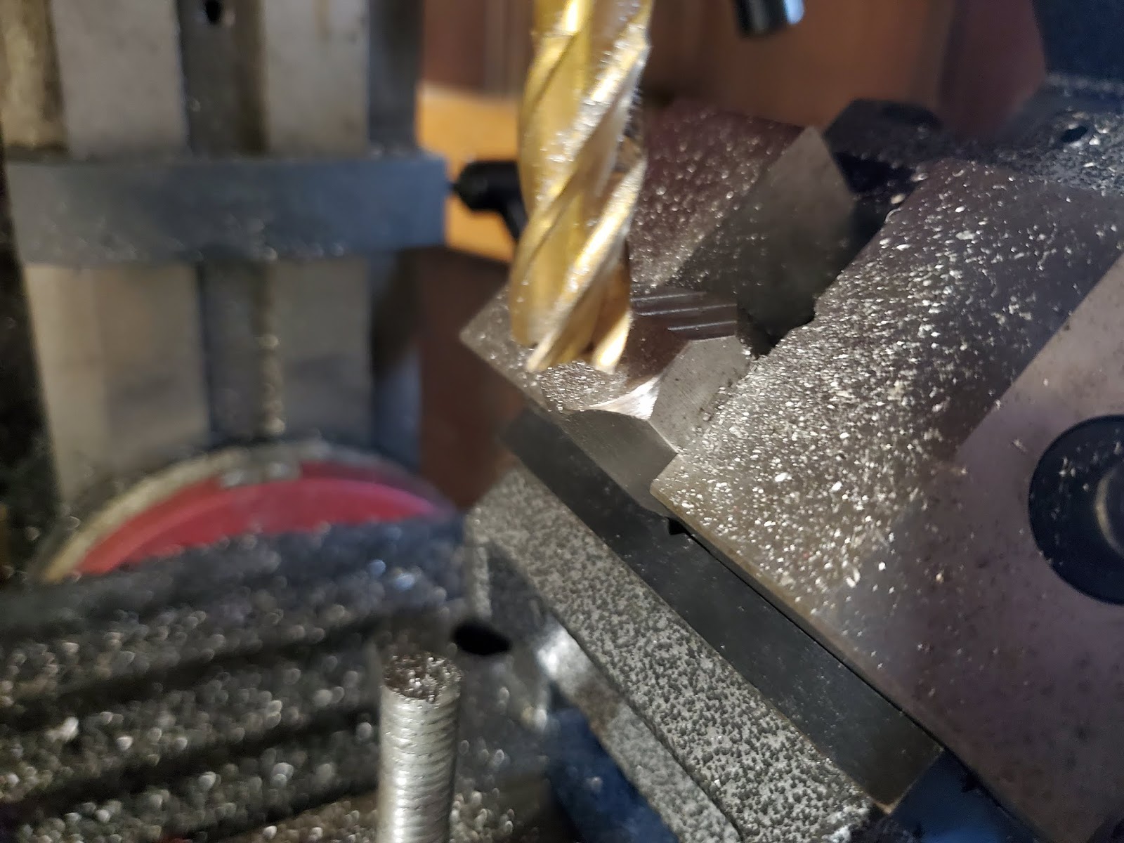
This time, I took a chunk of aluminum round bar.  This was the easier way to do it, anyway.  I used the lathe to drill the first hole (much longer than the first time, because I can cut stock off if needed).  Then I turned it down for the shoulder, and subsequently turned down the threaded portion and installed the thread.  After that, I put it in the mill and put three flat faces on there (two so I can use a wrench to get it tight enough, and one for the face that will have the intersecting hole).  I did the parallel faces first, followed by the intersection next.  With the last face done (and while it was still in the mill), I used a 5/16" end mill to put a hole in it, then a 3/8" part way in, followed by a short stint on a 7/16" end mill.  See, this one has to be a 3/8" pipe thread, which has a taper, and the different sizes will get me close enough to use a pipe tap.  I then started the pipe tap using a straight-shank center in the same 3/8" collet, and put the tap in place and began cutting.


I think this iteration is going to work just fine.

Sunday, September 6, 2020

Good News and Bad News 2020

 I have good news and bad news.

That's not true.  I have great news and okally-dokally news.

Before I could get it to run on it's own, I had to drop the 18 PSI fuel pressure down to 8.  I installed a fuel pressure regulator for that, and then it only took an hour to get it "running".  The Corvette has now been started on it's own (no more pouring fuel down the carburetor throat).  The timing was 4 degrees after top-dead center.  It makes a difference when you advance it enough.  Right now it's at 8 degrees before top dead center - I need an additional 4 degrees advance, but it still runs.

Now for the okay-dokally news.  There are a number of issues I need to work through before I run it again.

First, the radiator hose is 1.510" on the inside diameter.  The radiator is 1.131" on the outside diameter.  Yes, it didn't just "leak", it flooded my garage.  That's okay.  I just need a Gates 26390 hose reducer.  It should go from a 1.5" size to a 1.25" size.  That problem is "solved", but is waiting on parts.

Next, I need to work on the fuel delivery.  The engine runs best with the idle mixture screws in all the way (barely seated).  That's not right (hear me out - it's really not).  It means I have fuel coming from somewhere.  The main jets don't engage until you have a little more pressure (your power circuit for fuel).  So, it's not my jet sizes.  The throttle plates are probably going to need adjusting,  to get the transfer slot mostly covered.  I know the secondary throttle plates are good.  The primaries I cannot see, so I'm going to have to take off my carburetor again.  If I am going in there, I probably need to do some work on my metering panels.

I want to (while I have it off) check that I have the power valve blowout protection, and get some new power valves in there to make sure that isn't my problem.  The symptoms align with the power valve being blown.

I need a ported vacuum for the distributor vacuum advance.  I need to install that to my fuel metering panel.  It looks like it has everything there (channels, etc).  I think it will be just drilling the fuel metering panel out and installing a hose flange for the distributor.

A little more information.  The intake manifold, 14057053 GM CFM 43, is for some 350 CUI blocks.  It's a spread bore intake.  I have a spread bore adapter for a square-bore carburetor.  Note, I still have my "Holley Contender" intake manifold from my old 350 CUI engine.  It is a dual-plane 300-38 (701R-38) "dominator" intake manifold.  If I remove my carburetor to handle the power value blowout protection, I'll probably swap that in.  Here's the "Contender" information :


The carburetor is a LIST-7010 carburetor (4160-style).  It has a secondary metering panel installed to it, center-hung floats (fully adjusted now), and should flow 780 CFM on it.

This thing should be able to idle smoothly.  Let's get started tuning it!

Monday, August 17, 2020

Corvette Fuel Line Connected

 I've been struggling with the fuel line for the 'vette.  With the carburetor sitting on it, I either needed to replace the carb, or custom build a fuel line.  I did not want one of those "adjustable" pieces of garbage, and no one made a dual-inlet fuel feed line for a carburetor that was modified with another fuel metering block (you know, because I changed from a vacuum secondary to a full fuel secondary).

I started out with one of those $30 dual inlet adapters that claimed it would fit (9.375" between inlet centers).  It was 0.250" off, so I tried to bend it to fit, and ended up with a fuel leak in some pin holes.  It was very thin wall, cheap, and had poor results.  That went into the trash fairly quickly.

Next, I bent some solid 3/8" stainless fuel rod, and milled a "y" trunnion.  Unfortunately, it never set right.

I bought a kit from Summit Racing that supposedly fit.  I mean, it had to work, right?  It had the 9.375" center-to-center, and listed a 5/8-18" inverted flare fuel inlet.  Turns out that's what fed from the fuel line.  When Summit Racing says "fuel inlet", that's not necessarily the fuel inlet.  Yeah, it's all wrong.

My final attempt was steel rod and a T block.  It took some effort flaring and bending the setup.  However, when I was done, it all fits, and I don't have a weighted system hanging on some rubber hose that will crack faster than a password in War Games.

And, with it all connected up :

Yes, I used some heat wrap on the fuel line.  I should have used it all the way to the carburetor, but I just didn't.  Now I gotta get the battery charged, and I can give it a shot and see if she runs on her own so I can tune the carburetor, then get the engine timed, and then ensure I have the transmission set up properly.

Friday, July 31, 2020

2014 Dodge Ram Integrated Trailer Brake Controller

I like factory looks on things.  I love adding accessories, but only if they have that original feel.  Case in point, all of my lathes.  The anomaly is the corvette.  Anyway, I needed to be able to haul my in-laws trailer after their truck experienced issues, and wanted a trailer brake controller.  One (factory look) plus one (wanted brake controller) equates to pay-a-way-over-priced-dealer-or-partially-overpriced-parts-and-do-it-yourself.  Add in the third variable - I'm cheap - and it just happened.  $400 later, and I saved $200.  Can I tell my wife that it was on sale, so it should be okay?

You absolutely HAVE to have the two connectors in the wiring harness for this to work.  For a picture of those, scroll down to the bracket photograph - they are the ones covered in a foam protector.  Anyway, here are the parts :
  • Three screws to attach the bracket to the dashboard frame - DO NOT USE PHILLIPS, SLOTTED, OR TORQX screws - you won't get a screwdriver on them (or a ratchet)
  • Switch itself (part # 68105206AC for a 2014 ram 1500)[the big switch bank [with the tow-haul button] is part # P56054468AA, in case you break that - don't ask me how I know.
  • Control module (part # 68092738AD)
  • Bracket (not sure of a part number, but a tag with a handwritten note had 68160146 if I read that right, see below)
Tools :
  • 7mm combination wrench (if you h]ave one that ratchets, use that)
  • 10mm socket and wrench (for the battery cable)
  • Phillips screwdriver (for the switch bank removal)
  • Small slotted screwdriver (to disconnect tabs)
  • #20 torqx bit (either screwdriver or ratchet wrench/socket, for the small tray at the top)
  • Tiny hands
  • A good vocabulary (see previous tool)
Here are pictures of the parts to the kit :


It's a 2014 Ram 5.7l (everyone says "Hemi", but I don't think it is) 1500.  I ordered the parts, and set to work.  There are a number of videos out there on the installation.  I liked the briansmobile1 video up to the point he used electrical tape instead of the third screw - and he had a dealer make the configuration change.  Another video seemed great, including the configuration change using AlphaOBD (https://www.youtube.com/watch?v=ffRD_zovKAM) - that's what I chose (because I didn't want to spend $200 and wait for 2 hours).

Briansmobile1 indeed skipped that top forward screw - and with good reason.  It is painful. I don't want to show my hands after that.  Brian shows running the screws in before any installation to get the bracket threaded.  This is a MUST!  It will allow you to get the screws started using fingers.

After the preparations (threading and disconnecting the negative battery cable using the 10mm), I began.  I pulled the dashboard apart.  Yes, that's my stereo - I had a short and wanted to see if I could solve that problem while I was in there.  Turns out, you find a lot of stuff.  My radio connector on the back wasn't completely connected.  It snapped in.  I found a Camel cigarette wrapper buried in the dash.  I was missing two screws.  I found three wires just hanging out (those were under the steering column).  It looks like this had been in an accident, and had a new wiring harness that had some unused wires.  Oh, well.


With the dash taken apart, I swapped out the switch.  It's an easy change, just four screws, pull the whole switch bank panel, and then pop out the old and pop in the new.  Then re-insert the panel and screw it back in.  Don't re-install the whole center dash panel yet, though, as you will need to put the bracket in.


Next, the bracket.  This shows that I have those two connectors for this to even work, and where that bracket goes.  It's in the drivers foot well (under the steering column, yes, you need to remove that, too).


I started the bracket using that forward/top screw.  It's the painful one that everyone seems to skip.  I had to use the open end 7mm wrench to make it work, and it was very much a contortionist experience.  My hand came out raw and scraped, but once that screw is in, I did the others with less stress.  Expect that bracket to take the longest time.

After getting the module bracket installed, peel off the foam from the connectors, and install the controller module and the two connectors.  Re-install the lower dash panel.  And then plug those center console connectors in.  Make sure they clip all the way in.


With that, you can snap the center console back together, and re-install the top "coin tray" screws.  I was missing those, so i had to go to my hardware bin.  You can take a moment to step back and gaze in amazement that you didn't shoot the truck and leave it for dead with that painful bracket screw from earlier.


Yes, that looks dark.  When doing this on a black truck when the outside temperature is 102.8 degrees Fahrenheit, you start going indoors to cool back off.  It takes longer.

Next is the AlfaOBD install. I used an OBDLink MX+ bluetooth (don't do the wifi version).  Also, thinking I could use the demo version as it claimed to have all the functionality, I ended up paying the $50 for the app because it will not do a car configuration change in demo mode.  There are four changes to make, and when you are done, it should be fully functional.
  • CustSetMenu 2-Trailer selected CSM
  • CustSetMenu 2-Trailer name CSM
  • CustSetMenu 2-Trailer type CSM
  • P/T Chassis Net-ITBM/HWM Integrated Trailer Brake Module
So, after all of that, I kept seeing the check engine light (I hadn't started the truck yet), and grabbed the codes.  I was getting a U113B (lost connection to switch bank module), and I have a random yellow wire hanging out :


It turned out the switch bank (next to the brake switch) had a broken connector lock, so it came loose.  That's what the U113B was telling me.  I made a quick repair (I didn't want to spend another $60 on that module, so I used a soldering iron to melt the clip back together and then used electrical tape to ensure a solid connection).  That part number (for my own future reference if the "fix" doesn't hold up) is listed in the following picture :


Looks good, and it triggers properly!

Tuesday, March 17, 2020

Custom Fuel Line for the 'Vette

I have a problem.  I have an engine from 1974, a car from 1977, an intake from 1985, a carburetor from who knows where, and I need to run a fuel line.  I've tried a few "stock" ones, but they don't quite fit.  I really want to avoid that stupid hose underneath the braided stainless that shifts, moves, and vibrates its way into rot and crack.  It has been a bit frustrating to say the least.

My brain finally had the answer - build one.  The carburetor is a dual-inlet carburetor, and the inlets are not horizontal - they angle down toward the engine.  Also, to the front of the engine is a water hose adapter to help cool some parts - I have to route around that.

Here's what I need to do :
  1. Make a trunnion to bring the three fuel lines together
  2. Bend the fuel lines into shape
  3. Solder the lines into place

Trunnion:

My biggest concern is the union of the three tubes.  I bought some stainless steel fuel line, and I bought a chunk of 7/8" stainless steel hex bar.  I sliced a piece off, about 1.25", chucked it into the lathe and faced it (and chamfered it).  Then I flipped it, drilled a 3/8" hole in about 3/4", and added a bevel for aesthetics (seriously, it was the weight, since this was going to be floating as a solid piece when I was done).


Then I took it to my mini mill, and set it into vise in a vise (tool makers vise at 90 vertical in all angles, then that tool makers vise put in the angle vise at a 45 degree angle on the flat end).  This allowed me to mill off a surface and then drill another hole into the back side at a 45 degree angle.


Once that hole was deep enough, I pulled the tool makers vise out (part still in it), and secured that to the mill table.  This allowed me to find the next hole parallel to the first one put in on the lathe.  I used a series of drill bits until I broke through, and then had to switch to an end mill.  Being the mill with the tables locked in place, it was right on, so changing the tooling didn't matter.


Now I have the trunnion.  I need to get it cleaned and degreased, but I was able to run a quick test fit.


Bend the Fuel Line 

Next up I need to bend the fuel lines.  I have three lines that merge into the trunnion.  The two feeding the carburetor need to bend toward the carburetor (one is a 90 degree bend, the other a 45 to match the angle of the trunnion), and then have a second bend in both of those to match up with the angle on the carburetor inlets (about a 60 degree bend) and to keep the line from interfering with the intake manifold.  On the other end of the fuel line, I need to bend over the front of the engine and go down to the fuel filter and pump.

First, I need to cut off a chunk of fuel line for each one of these rods.  I'm going to cut more - it's easier to have too much than not enough, and right now, I'm not quite sure where things are going to end up.  I'll cut things about two inches longer on each end than I need, then I can cut things down prior to soldering.

Soldering

I'm not using electronics solder - I doubt it will hold up to the vibration.  That leaves welding solder and jewelry solder.  Both should work (both are based on silver solder, and should have the strength I need).

Saturday, March 14, 2020

Electric Choke Conversion

My old Holley Carburetor had an electric choke on it.  The "new" one had a manual choke. I didn't want to punch a new hole through a firewall and dash board to install a manual choke cable, so I bought a Holley 45-223 conversion kit.


First, you have to remove the old one.  The kit comes with instructions, but not a lot of pictures, so I got a bit stymied on a few things.  As you take the old one off, there are a few things you want to save (these are re-used on the new choke) :

  • The screw in the choke cam (mine did not have a spring, it was a plastic choke screw, so I used the marine screw provided and made the adjustment with that)
  • The clevis pin holding the manual choke mechanism to the choke rod (this is a tiny pin - don't lose it)
  • The fast idler cam screw

So, start by removing the three screws holding the mechanism to the carburetor body.


Next, remove the clevis pin holding the rod to the choke body.  Set this aside, as you will swear at me if you lose it.


Remove the fast idler cam screw, and set this aside, because you are going to need it later.


Remove the fast idler cam mechanism - it just slides away from the carburetor body.  While you have the cam mechanism, remove the screw adjuster and set this aside, too.

The manual choke housing is made of two plastic parts and some linkage.  You can either discard them or hang on to them if you ever want to change it back to manual, but please wait until the installation is complete before discarding anything.

Next, it's time to start the installation.  The kit comes with two square-looking cork gaskets with a hole in them.  The gaskets are not actually square - there is a ring cut into the cork - that is what you will need, and you need both of them.  Where the rear screw attached the old housing, there is a small port on the carburetor body.  This is the choke vacuum port.  Clean the surface on the carburetor.  Once clean, take one of those square cork "gaskets", and peal the backing off.  It should stick. Note, it could be so old that it doesn't - that's my experience.  I used an extremely small dab of grease to secure the gasket in place.


Next, install the cam - the instructions here are pretty good - you just need to remember to use the cam adjustment screw from the manual choke, along with the fast idler screw that holds it in place.  Follow the directions (they have three pictures in the instructions that show orientation and setup fairly well).  Then, install the fast idler screw to hold it to the fast idler shaft.  That is a rod with a slotted end to fit and lock it all in place, so make sure you get it seated properly.


Take the other gasket, and fix it to the back of the new electric choke hosing.  It took me a minute to find where it went, as I kept looking at the inside (the concave side).  You'll be looking at the side with the red plastic cam.  There are four "tubes" coming off on that side, three are for screws to attach it, and the other will have a little brass "bushing" inside with a very small hole.  That is where you'll put the second round, cork gasket.

Next, install the metal cam to the choke rod.  This takes three hands working with good coordination, or two hands if you want to cuss a little.  Once in position, attach the clevis pin from the original manual choke.

Now you can lift the red cam as you set the choke housing into place using the three screws to ensure the correct position.  When done, you should be able to move the choke in the carb and see things move in the choke housing (there's a little rod that sticks out from the housing).  Make sure the red cam is on top of the fast idler mechanism.  You may be able to reach behind the choke housing and wiggle the cam to ensure it is in a good spot.


Next, install the actual choke cover (the plastic piece that has the bi-metallic strip inside).  To do this, set aside the screws to hold the cover down within reach of where you are doing this, because you'll only have one hand.  Put the metal retaining clip (that has the three screw slots) over the outside of the cover with the concave side out (meaning the screw holes are going to be farther out than the edges in between).  Set the round gasket into place into the housing (it's easier than manipulating the retaining ring, cover, and the gasket while trying this.  That strip has a small ring on the end.  Here's some trickery, because as you install it, you have to get the bar sticking out of the housing into that ring.  I'd immediately (while holding the cover in place) grab one screw at a time and get it far enough in position (but not too tight) that it holds it all together.


You should still be able to turn the cover, and see the choke cover open/close (do both to make sure that strip and shaft are properly seated).  Once validated, turn the cover until the marks on top of the housing and the cover line up, then you can fine-tune the choke from there.  When "cold" (e.g. not having been connected to the battery for a few hours or so), you want the choke plate to be barely open (a #2 pencil is what Holley recommends as the starting point).  Then, tighten the cover screws until you can't turn the cover.


Now, you can do the electronics.  I ran the negative side to one of the carburetor bolts.  The other one (the red one) should NOT get attached directly to the battery (or any other always-on connection), as that will completely negate the choke and drain your battery.  You want to tie it to an on/run wire so that it is only at 12 volts when you are running the car.  As soon as you turn the key to the on position, the strip will start heating up and open the choke plate.  It doesn't matter if you actually DID start the car, it's going to start moving.

Sunday, November 24, 2019

Wrong Intake, and Making Custom Gaskets with a Silhouette

While trying to get the corvette started a few weeks ago, I found an oil gusher coming from an exposed oil hole on top of the engine block.  It's not the original engine, but it is the original intake manifold.  Please note, it IS a first generation small block.  My mistake was to assume that all first generation small blocks are identical or compatible.  They are not.  So, it was time to do some decoding.  I grabbed pictures of the ID numbers on the block and on the intake, just to make sure I had the details.


Here's the firing order, just to post it for posterities' sake.


The block offers a little more detail.


So, I have a 14057053 intake manifold (lots of virtual links to 1980-1985 Chevrolet 305/350 engines), and the engine block has V0228TKS engine code that matches a VIN of T4U511082 .  The block ID of V0228TKS looks like it was made in Flint, Michigan.  The 0228 are a date stamp, meaning February 28.  The rest of the letters (TKS) on the end indicate it was a 1974, 1978, or a 1980 small block, and destined for use in a van or truck (on really old engines, the three letter code starting with a "C" for cars and "T" for trucks).  Prior to 1970, the suffix codes were only two digits.  So, we know we are at least 1970 and later.

The VIN part helps us isolate it between the 1974, 1978, and 1980 model years.  The start of it indicates the manufacture target even more.  Starting with a number 1 would be for a Chevrolet, 2 would be for a Pontiac, C for a Chevrolet truck, and a T for a GMC truck.  The second digit of the engine VIN represents the last digit for the year code (number in the 1970's, letter in the 1980's).  The next digit (a letter) represents where the block was manufactured.  I have a "U".  The rest of that VIN code should match to the last digits of the vehicle the engine went into, so I don't care about that.

So, this was a first generation small block engine that was made February 28, 1974 in Flint, Michigan for a GMC 350 truck that was assembled in Hamtramck, Michigan.

I ordered a carburetor adapter for a holley 4160, I know to order one for a 1974 GMC C10 350 cui.  It was for a rochester system.  However, it did not fit.  At all.  It turns out the intake was for a spread bore (sometimes I don't know why my brain doesn't work).  So right here, I went off on a tangent.  Scroll down for the results if you don't care to know how to create a custom gasket for something.  Search for "end of the tangent" to get past all of this gasket making stuff.

Anyway, I decided to cut a template to take with me to the parts store and see if anything would fit.


Time to break out the Silhouette - mans best friend for custom gasket making.  Here's what we need to replicate into both a pattern for the adapter :


Before cutting, you do have to design it. Grab a blank piece of paper and a crayon (or a colored pencil, basically anything using wax or lead, but crayons are seriously the best).  Carry those to the flat surface you want to replicate (you know, the intake manifold's carburetor surface), and place it on there.  While holding the paper still (so it doesn't move during this part of the process, or it won't match), carefully rub the crayon over the surfaces.  The corners will have a darker edge where the crayon wants to roll over to the paper where there is no surface below the paper.  This is precisely what you want.


Once you have the paper finished and can see the entire surface (you really want the edges highlighted), you can now transfer that paper to a scanner.  If you don't have one, libraries or friends with scanners can come in handy.  You do need to scan it for this process.  Granted, you could simply cut it out and use it as a pattern on your gasket material, but you don't get to do some seriously manly stuff like using a craft cutter, I mean, using a CNC cutter in making perfect gaskets.  So, load the scanned image into your editor (Photoshop works, but I like open source software and always use Gimp), and adjust the levels (sort of like a brightness/contrast, but better control over where the levels sit for it) :


Awesome!  Now we have a scanned image that we can see the edges with!  Save it out, and open another open source package, Inkscape.  If you've never used Inkscape before, you might need your wife to show you.  Granted, you can probably use Silhouette Studio upgrade for this, but old habits die hard and I have the basic studio, so I can't.  The intent here is to convert those visible edges into bezier curves.  Essentially, you are tracing a bitmap into shape :


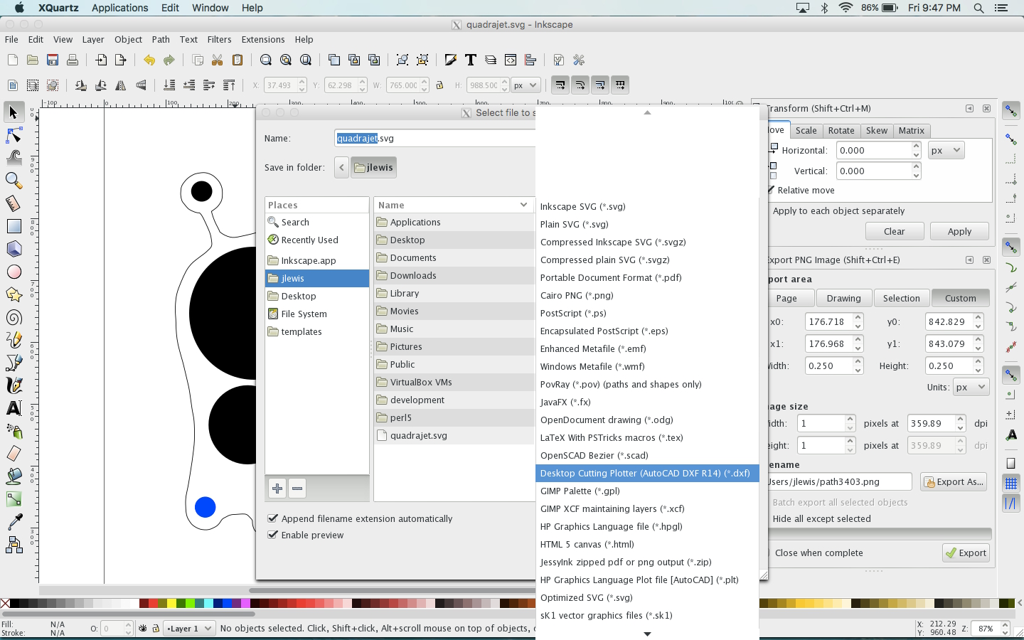
Now, save your SVG, even though we don't really need the SVG.  Once saved, export it into a DXF (plotter/cutter).  This format can now be imported into Silhouette.  Open Silhouette Studio, and import it into your library.


Once in, you can insert the object into a new project.  I would suggest immediately selecting everything, clicking on object, and grouping them together so it is less likely to move one curve out of place.  Make absolutely sure that there are no cut lines across the resulting gasket before proceeding!  I'd get another blank piece of paper and load it into the silhouette, and send it to the printer at this time.


Grab that newly-cut piece of paper, carefully peel it off of the cutting board, and take it to your part to ensure it has the right fit.


The odds are not in your favor of having it fit perfectly the first time.  This is why we do a test piece, first.  Determine the adjustments, make them in Silhouette, and try again.  Keep doing this until you have the right fit.


Now, load your template material, adjust the Silhouette's depth of cut, and cut out your final template.    If you are making not just a template but a gasket, that's just fine, too.  Congratulations, you just made a custom, professional gasket for your engine!  Anyway, that's the end of the tangent (this is where that search above would bring you).  So, back to my case - I'd successfully located an adapter (though I'd rather try the Edlebrock spread bore to square bore adapter kit as it doesn't nullify the intake's separation of primary-vs-secondary chambering.

So here we go.  My intake used 3/8-24 bolts.  This Mr. Gasket (#1932) adapter was built for 5/16 bolts.  This is definitely not going to work.  But, I had a drill press, a letter 'U' drill bit, a 3/8 drill bit, and a 9/16" end mill (square, this is important).  I grabbed the adapter and ran over to the drill press.  Make sure the drill bits will extend into the drill press center so you don't drill holes in your table, get the table to the lowest you can do for your drill bit to get all the way through the adapter.  Lock the table into place.  I am using a 3/8-24 socket head bolt (so I can use an allen to tie the adapter to the intake.  So, what I've got to work with :


I first used the U drill bit to fit through the hole (drill press not running) and line the adapter up with the drill press spindle while clamping the adapter to the table.  Then you can change drill bits to increase the size of that exact hole to 3/8".


You'll find after a test fit that the bolts now fit through the hole (see above), but do not seat into it (the heat hole is too small).  This is why I used a 9?16" end mill - the socket head is just shy of 9/16" in diameter.  So, remove the drill bit (do not unclamp the adapter to move to the next hole because you'll lose the reference of the hole to the spindle), and put in the 9/16 end mill into the chuck.  Don't worry about it not clamping hard enough on the end mill, the adapter should be aluminum, and we're not putting side loads on it (we're only trying to drill a flat-bottomed, 9'16" hole for the socket head).


With that in place, slowly peck away at that hex socket until we reach the bottom of it (do not proceed below that seat that originally existed).


When done, you can test fit the bolt into the adapter :


You will note that the socket head sits slightly proud of the surface.  This will have to be remedied to be used.  I installed the 3/8" collet into the lathe and faced the bolt until I had the right height.  You can easily use an angle grinder to eat away at it until it is low enough.


Now, it's time to install the adapter.  It should be fairly easy.  Just drop the gasket into place, set the adapter on (in the right direction, of course), and install the bolts (don't forget to have the other bolts in place before you install the adapter).


With the carburetor bolted down :


Next up is to run the fuel lines.  In the above picture, those lines are going to be replaced. They are terrible.  I have to bend them to match the angle coming off of the carburetor so I can clear the block off plate and the A/C fitting toward the front.  Here, let me circle those for you :


So, I need to custom run a fuel line.  I do not want to be replacing rubber every few years, so I have to go with a hard line.  Because the newer, non steel lines would require supports, I have to do either straight steel or stainless steel.  We'll see where I get.