


Here's the firing order, just to post it for posterities' sake.

The block offers a little more detail.

So, I have a 14057053 intake manifold (lots of virtual links to 1980-1985 Chevrolet 305/350 engines), and the engine block has V0228TKS engine code that matches a VIN of T4U511082 . The block ID of V0228TKS looks like it was made in Flint, Michigan. The 0228 are a date stamp, meaning February 28. The rest of the letters (TKS) on the end indicate it was a 1974, 1978, or a 1980 small block, and destined for use in a van or truck (on really old engines, the three letter code starting with a "C" for cars and "T" for trucks). Prior to 1970, the suffix codes were only two digits. So, we know we are at least 1970 and later.
The VIN part helps us isolate it between the 1974, 1978, and 1980 model years. The start of it indicates the manufacture target even more. Starting with a number 1 would be for a Chevrolet, 2 would be for a Pontiac, C for a Chevrolet truck, and a T for a GMC truck. The second digit of the engine VIN represents the last digit for the year code (number in the 1970's, letter in the 1980's). The next digit (a letter) represents where the block was manufactured. I have a "U". The rest of that VIN code should match to the last digits of the vehicle the engine went into, so I don't care about that.
So, this was a first generation small block engine that was made February 28, 1974 in Flint, Michigan for a GMC 350 truck that was assembled in Hamtramck, Michigan.
I ordered a carburetor adapter for a holley 4160, I know to order one for a 1974 GMC C10 350 cui. It was for a rochester system. However, it did not fit. At all. It turns out the intake was for a spread bore (sometimes I don't know why my brain doesn't work). So right here, I went off on a tangent. Scroll down for the results if you don't care to know how to create a custom gasket for something. Search for "end of the tangent" to get past all of this gasket making stuff.
Anyway, I decided to cut a template to take with me to the parts store and see if anything would fit.

Time to break out the Silhouette - mans best friend for custom gasket making. Here's what we need to replicate into both a pattern for the adapter :

Before cutting, you do have to design it. Grab a blank piece of paper and a crayon (or a colored pencil, basically anything using wax or lead, but crayons are seriously the best). Carry those to the flat surface you want to replicate (you know, the intake manifold's carburetor surface), and place it on there. While holding the paper still (so it doesn't move during this part of the process, or it won't match), carefully rub the crayon over the surfaces. The corners will have a darker edge where the crayon wants to roll over to the paper where there is no surface below the paper. This is precisely what you want.

Once you have the paper finished and can see the entire surface (you really want the edges highlighted), you can now transfer that paper to a scanner. If you don't have one, libraries or friends with scanners can come in handy. You do need to scan it for this process. Granted, you could simply cut it out and use it as a pattern on your gasket material, but you don't get to do some seriously manly stuff like using a craft cutter, I mean, using a CNC cutter in making perfect gaskets. So, load the scanned image into your editor (Photoshop works, but I like open source software and always use Gimp), and adjust the levels (sort of like a brightness/contrast, but better control over where the levels sit for it) :


Awesome! Now we have a scanned image that we can see the edges with! Save it out, and open another open source package, Inkscape. If you've never used Inkscape before, you might need your wife to show you. Granted, you can probably use Silhouette Studio upgrade for this, but old habits die hard and I have the basic studio, so I can't. The intent here is to convert those visible edges into bezier curves. Essentially, you are tracing a bitmap into shape :


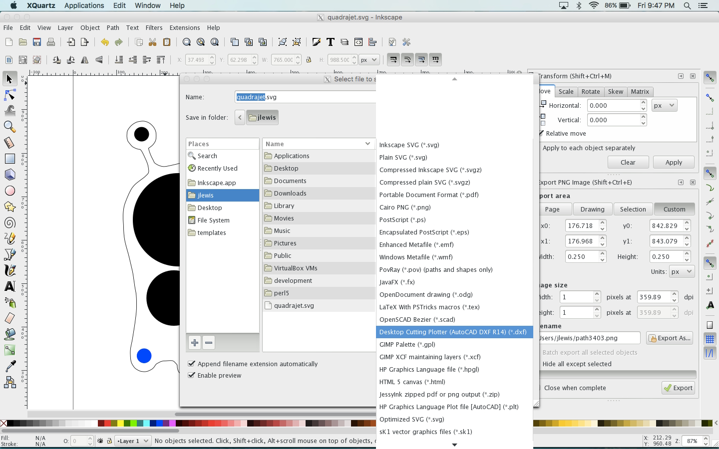
Now, save your SVG, even though we don't really need the SVG. Once saved, export it into a DXF (plotter/cutter). This format can now be imported into Silhouette. Open Silhouette Studio, and import it into your library.

Once in, you can insert the object into a new project. I would suggest immediately selecting everything, clicking on object, and grouping them together so it is less likely to move one curve out of place. Make absolutely sure that there are no cut lines across the resulting gasket before proceeding! I'd get another blank piece of paper and load it into the silhouette, and send it to the printer at this time.


Grab that newly-cut piece of paper, carefully peel it off of the cutting board, and take it to your part to ensure it has the right fit.

The odds are not in your favor of having it fit perfectly the first time. This is why we do a test piece, first. Determine the adjustments, make them in Silhouette, and try again. Keep doing this until you have the right fit.


Now, load your template material, adjust the Silhouette's depth of cut, and cut out your final template. If you are making not just a template but a gasket, that's just fine, too. Congratulations, you just made a custom, professional gasket for your engine! Anyway, that's the end of the tangent (this is where that search above would bring you). So, back to my case - I'd successfully located an adapter (though I'd rather try the Edlebrock spread bore to square bore adapter kit as it doesn't nullify the intake's separation of primary-vs-secondary chambering.
So here we go. My intake used 3/8-24 bolts. This Mr. Gasket (#1932) adapter was built for 5/16 bolts. This is definitely not going to work. But, I had a drill press, a letter 'U' drill bit, a 3/8 drill bit, and a 9/16" end mill (square, this is important). I grabbed the adapter and ran over to the drill press. Make sure the drill bits will extend into the drill press center so you don't drill holes in your table, get the table to the lowest you can do for your drill bit to get all the way through the adapter. Lock the table into place. I am using a 3/8-24 socket head bolt (so I can use an allen to tie the adapter to the intake. So, what I've got to work with :

I first used the U drill bit to fit through the hole (drill press not running) and line the adapter up with the drill press spindle while clamping the adapter to the table. Then you can change drill bits to increase the size of that exact hole to 3/8".


You'll find after a test fit that the bolts now fit through the hole (see above), but do not seat into it (the heat hole is too small). This is why I used a 9?16" end mill - the socket head is just shy of 9/16" in diameter. So, remove the drill bit (do not unclamp the adapter to move to the next hole because you'll lose the reference of the hole to the spindle), and put in the 9/16 end mill into the chuck. Don't worry about it not clamping hard enough on the end mill, the adapter should be aluminum, and we're not putting side loads on it (we're only trying to drill a flat-bottomed, 9'16" hole for the socket head).

With that in place, slowly peck away at that hex socket until we reach the bottom of it (do not proceed below that seat that originally existed).


When done, you can test fit the bolt into the adapter :

You will note that the socket head sits slightly proud of the surface. This will have to be remedied to be used. I installed the 3/8" collet into the lathe and faced the bolt until I had the right height. You can easily use an angle grinder to eat away at it until it is low enough.


Now, it's time to install the adapter. It should be fairly easy. Just drop the gasket into place, set the adapter on (in the right direction, of course), and install the bolts (don't forget to have the other bolts in place before you install the adapter).

With the carburetor bolted down :

Next up is to run the fuel lines. In the above picture, those lines are going to be replaced. They are terrible. I have to bend them to match the angle coming off of the carburetor so I can clear the block off plate and the A/C fitting toward the front. Here, let me circle those for you :

So, I need to custom run a fuel line. I do not want to be replacing rubber every few years, so I have to go with a hard line. Because the newer, non steel lines would require supports, I have to do either straight steel or stainless steel. We'll see where I get.


