Monday, May 30, 2022

"Repair" of a Harbor Freight No. 33 Hand Plane

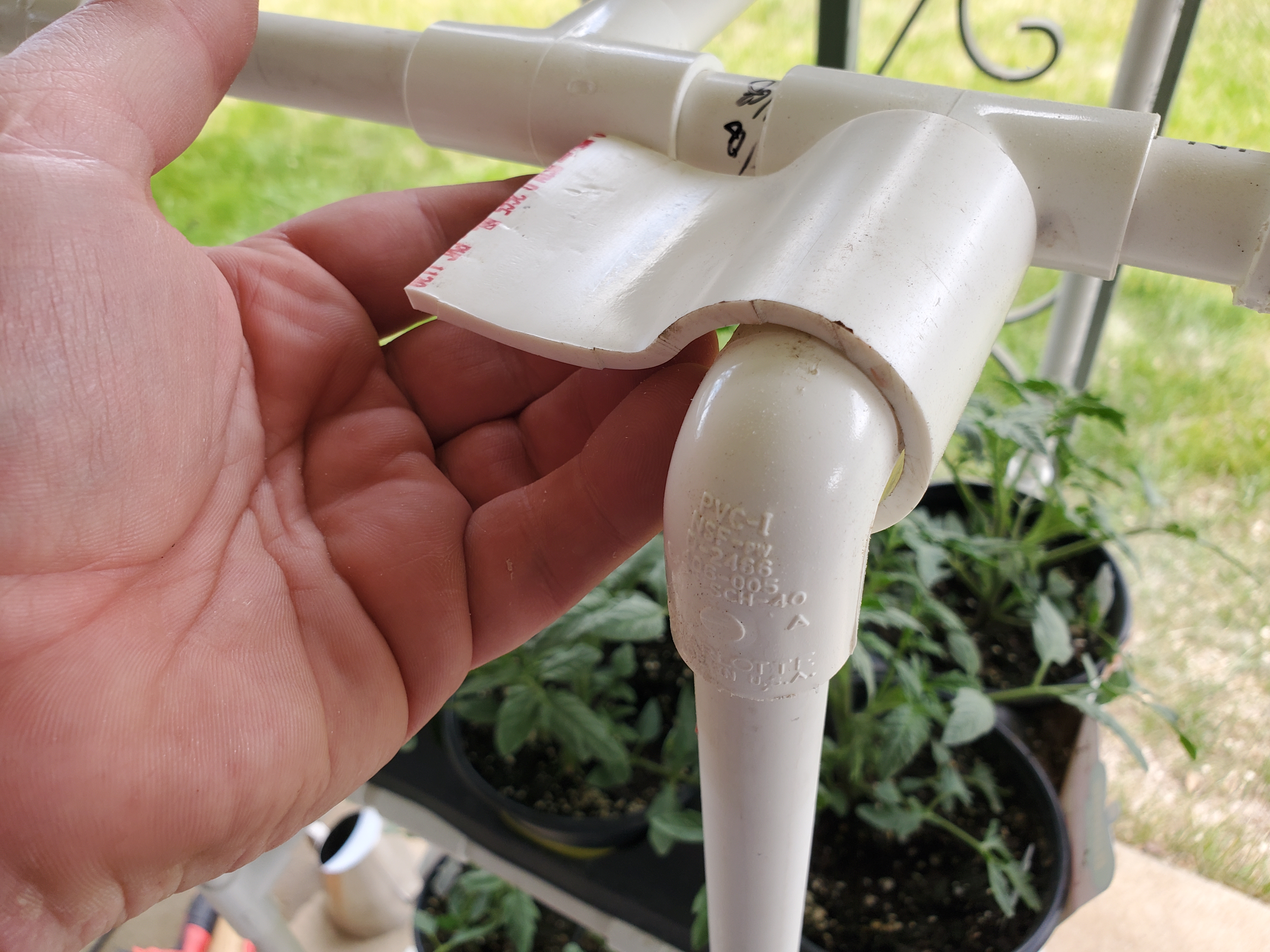
 I bought a hand plane back on the ol' table project from Harbor Freight.  While I could "manage", there are some issues with it.  The one that made it nearly impossible to use was one of the knurled nuts that adjusted the depth of cut on the blade.  I expect that someone made an adjustment on the parts for the threaded shafts from a 6x1.0mm thread to a 8x1.0mm thread (or the other direction - I can't be sure).

The one I bought had two 6x1.0mm threaded shafts, one 6x1.0mm knurled nut, and one 8x1.0mm knurled nut.

When I contacted Harbor Freight, they just said I'd have to buy a new one.  Bad customer service there (but that was an anomaly, possibly).  I set the tightness on the blade and muddled through the table project.  Not the greatest experience, but I coped.

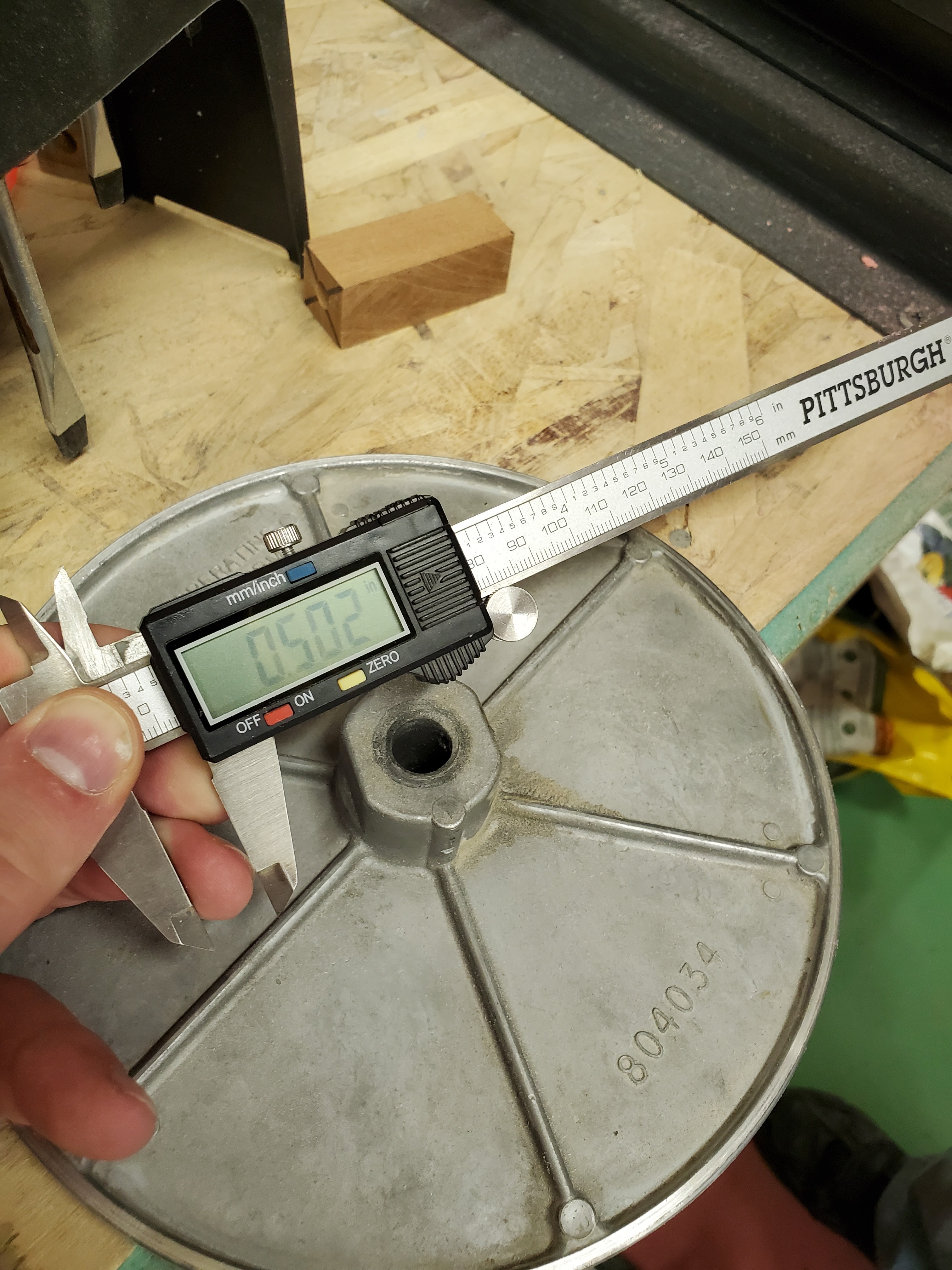
Well, I got tired of having that thing sitting around, so I took a few measurements, and made sure I had the 6x1.0mm tap on hand.  I rummaged through my collection of drops, and found a 5/8" stainless steel bar that I could use.  Should be fairly easy to whip through it (ominous foreboding), right?

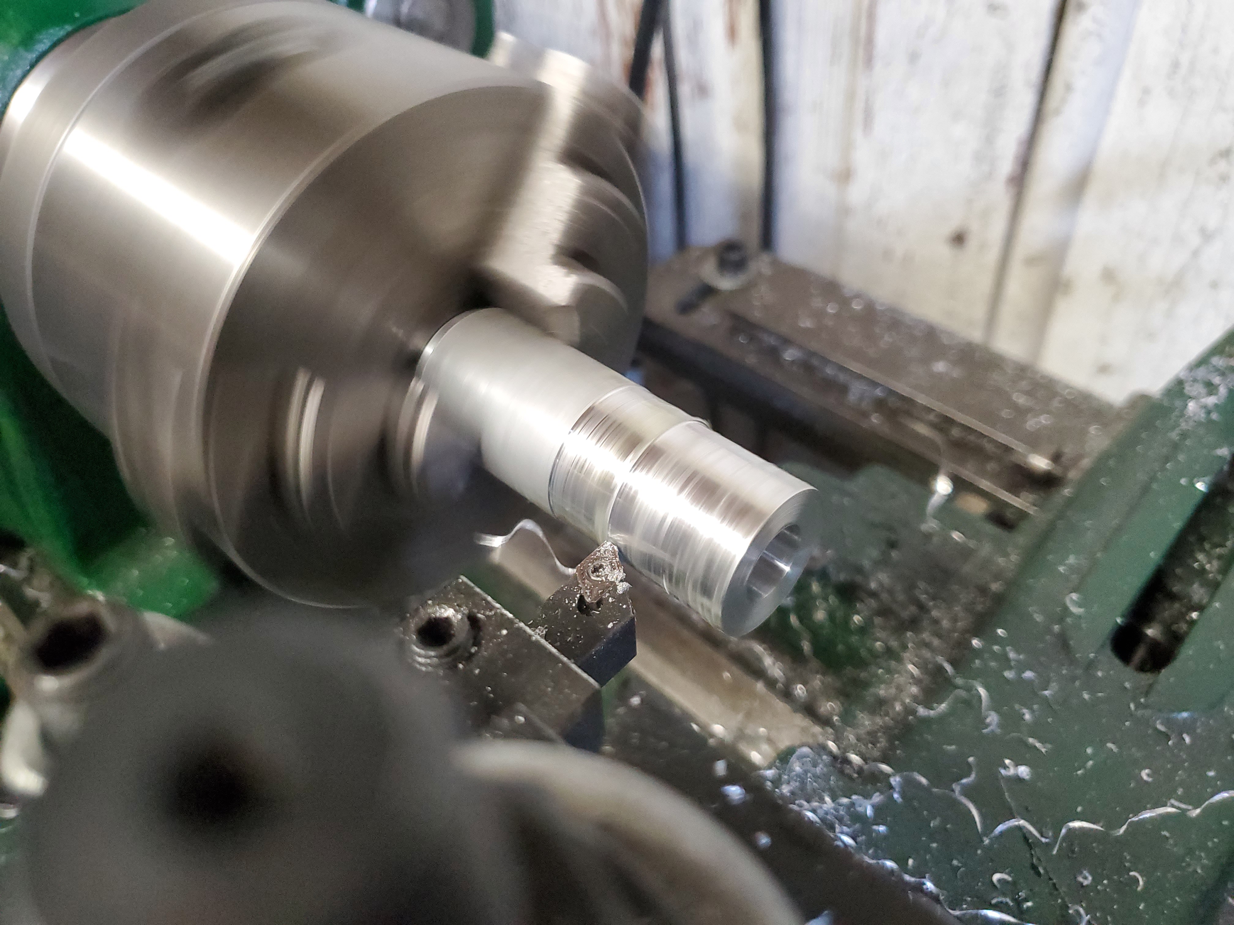
The bar was chucked into a 5C collet, and faced off.  Then, I drilled it with a #6 drill bit, which is 0.204" or (5.18mm, since this is a metric part).  As an FYI, a 5.2mm drill bit is the right size to tap aluminum.  I was even smaller, so I purely thought I could get perfect threads out of this.  I commenced tapping.

At some point, you cut your losses and give up on tapping this stupid part all the way through.  That's when I found the pre-existing part was NOT tapped all the way through, either.  When I measured to the threads, I found it was about a half inch or 12mm of thread.  I made the decision that I would stop trying to run threads at this stage, and drill for clearance later (after it was removed from the lathe so I could actually get to the back side of the hole), and then I'd hand-tap the rest of the way.

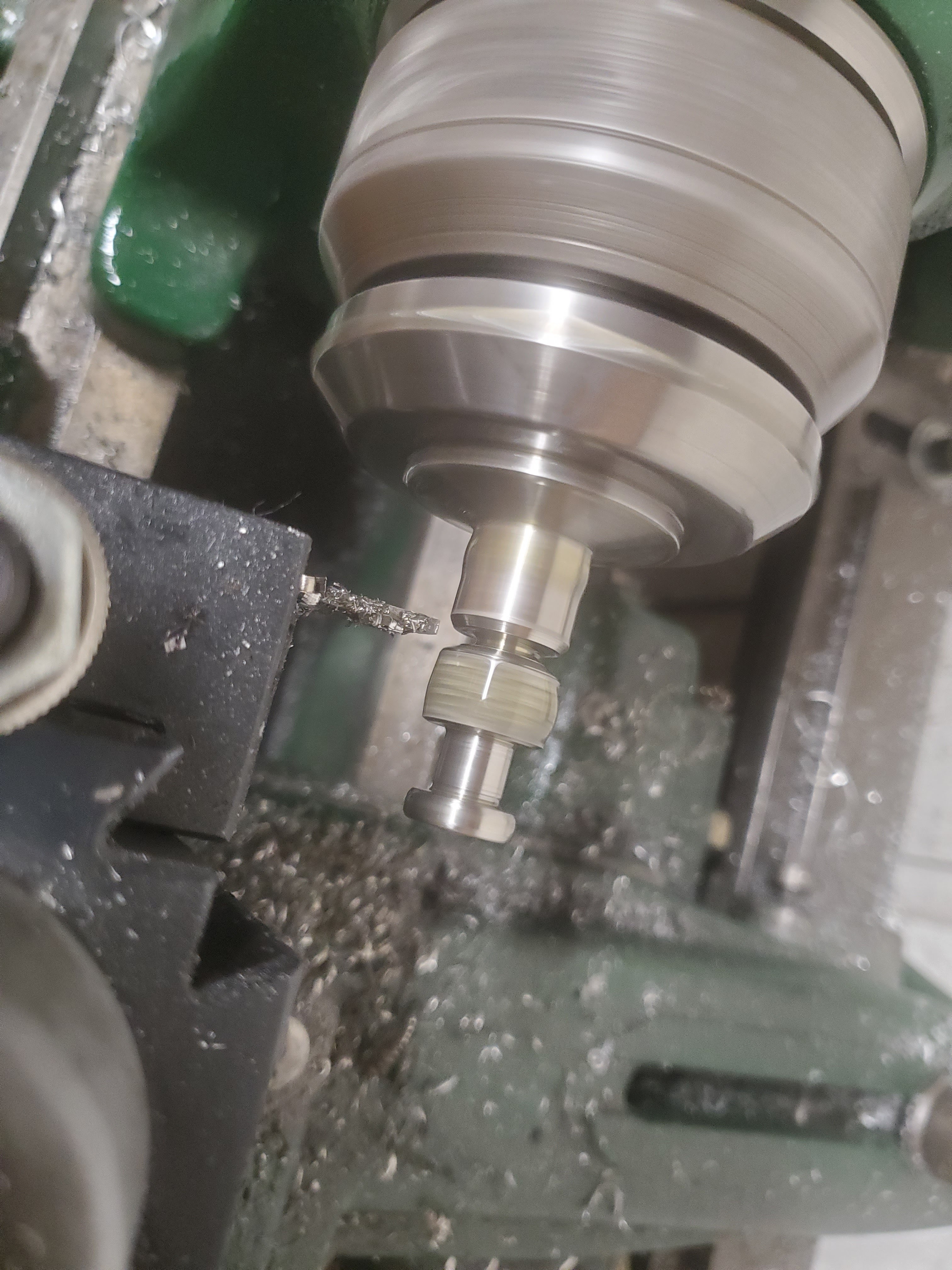
I moved on to the next step - knurling. I also took the time to do some knurling.  This was my first chance at using the scissor knurling tools, instead of the pressure knurling tools.  If you think your knurling is impossible, and you use the pressure knurling tools, just stop what you are doing and buy a scissor knurling tool.  Just do it.  You can thank me later.  Anyway, the knurl came out way better than any knurling I've ever done.

So, I finished the bosses and other dimensions.  The stainless sure is going to look good.

I parted it off.

I drilled out the back side until I had about 3/8" of thread meat left (that's 8mm, this is a metric part).  I then went outside and manually tapped this thing for another hour and a half.  This stainless is brutal!  But, I got it done.

I had to give it a fitness test, and yes, this is going to work.  I might need to do some more filing to get a perfect fit, but the reality is that this will suffice better than the original 8x1.0mm part.

You can tell which one is mine - it has the machined bevel on it (the one on the right side), so it's not a lazy casting of unidentified-origin metal.

This hand plane is now fully functional.  I might need to make a spacer for the wood handle so that it can be anchored, but at least it's usable now.

Friday, May 27, 2022

Shoulda Put a Ring On It

I finally got a chance to get my boring head into use and made some rings.  I REALLY like the ceramic comfort rings, but that stainless looks fabulous!

I gotta make some more - those disappeared into some family hands way too fast.  I ordered some replacements, and set the inlay using resin with a few different variations.  I love the look of the stainless steel, but just know that HSS lathe tools or carbide lathe tools will mark them up - it's just a given.  I've turned stainless using these materials in the past, so it just stands to reason.

I like the ceramic.  It seems to be less impervious to turning tools.  They don't come in silver, which is bad, but they still look good.  Anyway, the inlays were done using 5-minute epoxy resin.  I'd squeeze a small bit out, mix it up, and then mix in the Tru-Stone.  I'd asked my spouse what was wanted, and had colors all picked out.

After 5 minutes, I'd mix up another spot more, and drop that into the ring groove right next to the last drop.  I slowly worked my way around the ring until the entire inlay groove was filled.


I waited for a few days to let the resin fully cure.  I simply used a wood dowel to store them on while they cured and pull them inside at night (when it got cooler), and back out during the day to cure.


Once the inlays were set, I could turn them.  As I have two different sizes, I needed to use different bushings, so I ran through mine and then my spouses.

 I turned each one down at a time.  The results were great!


They are complete, and give a little variety to what I can wear each day.

Nice Rack!

 Alright.  Spring was normal, meaning it got hot, and then froze, and then got hot, and then froze again.  It makes it difficult to create a garden in the springtime.

So, I grabbed some PVC 1/2" PVC pipe fittings and pipe (nothing threaded, because I want to be able to put it into a box at the end of the season).  The lengths of the cuts were determined by the planter bins.  It just pushes together, and bingo - a grow rack.  I made three levels - each one has four 90 degree elbows, 12 tee's, and a few sections of pipe made to fit.  With it pressed together, I needed to add some grow lights.  I picked up some grow lights off of Amazon, and needed a way to anchor them.

With 1/2" pipe fittings, I grabbed a 1 1/4" PVC pipe, and I put a slit up the pipe lengthwise long enough to cut off pieces for my flat adapter (but not all the way, because I didn't want it collapsing on the table saw blade and ripping it out of my hands - that would have been a bloody mess). I then sliced off 2" lengths of that.

The pieces around the slot were then heated and bent to form some "half pipes" with a flange.  That flange was then drilled.  I sliced up a cutting board (DO NOT USE A TABLE SAW FOR THIS) to get lengths, and then drilled those to match.  They got screwed together.


I could then clip everything together and fire it up :


I know I'm about a month or two late, but next year should give us a garden early.

While there, I ran some 1/4" tube to automagically water the hanging flower pots.


These have valves to turn off individual off shoots, so it is perfectly controllable.  Garden ... check!

Wednesday, May 18, 2022

RGB Light Bulbs - Finally

 I've gone the rounds with Chinese hardware that is based way too much in the cloud, or with stupid configurations that are supposed to be "easy" but open your phone up to an application that presents your local Wi-Fi configuration to an untrusted application.  (It all started with a Feit Electric RGB light bulb from Costco, and just seemed to get worse from there.)

Then I found an Athom LB01 7 Watt light bulb on Amazon.  It's an E27 format, meaning it plugs into a standard light socket, and is based on the ESP8266 hardware.  That likely meant it was hackable.  So, I ordered two of them.

They shipped from China.  Not a good initial sign, but let's see what this thing has going on.

Starting out, the instructions had this set up list of six steps.  The first step was plug it in and power it up, and then find a new Wi-Fi called "Homekit_XXXX".  This was the first sign of life for these bulbs. That meant that these things were configurable using a web browser on a computer.... so no unsecured, trashy, untrusted phone application requiring access to all my phones data was required.  Woohoo!  Plug that thing in and turn it on.  Yes, indeed.  A new wireless network showed up :

I connected, and ran "ipconfig" to see what the gateway was.

    
    Ethernet adapter Bluetooth Network Connection:
    
       Media State . . . . . . . . . . . : Media disconnected
       Connection-specific DNS Suffix  . :
    
    Wireless LAN adapter Wi-Fi:
    
       Connection-specific DNS Suffix  . :
       Link-local IPv6 Address . . . . . : fe80::f5d9:f994:7e91:6c88%13
       IPv4 Address. . . . . . . . . . . : 192.168.4.2
       Subnet Mask . . . . . . . . . . . : 255.255.255.0
       Default Gateway . . . . . . . . . : 192.168.4.1
    
    C:\Users\Username>
    

So, I see it created a 192.168.4.X network.  I opened the browser and connected.

Then, I found this nifty little tab in the web interface on which a firmware could be uploaded.  On that about page is the MAC address, if you are going to add static DHCP addresses or allow a MAC onto your network.  Make a note of that.

Wait a minute..... that means that I don't even need to break it open to find soldering tabs to re-flash firmware?  Seriously?  This light bulb just got even better.  I have to just try a random firmware.

I grabbed the WLED firmware from some random page (I trust that more than I trust Chinesium, right?), and uploaded it.  It gave me a nice progress bar, and then the bulb turned off and then the browser went into a "can't be reached".  Of course, that thing had to reboot, so I expect that behavior.  I had to reconnect to the new network.

BTW, the default AP mode firmware password is "wled1234".  I'd change that quickly.  In my neighborhood, I may have trained a few neighbor kids to run amok with stuff like this.  Open a web browser tab, and point it to 4.3.2.1 after you've connected to WLED-AP.  The initial page is a classic 80's style look to it.

The first thing to do is click on the WIFI SETTINGS button.

The fields that are critical are the Network name and password, the mDNS address, and the AP SSID and associated password.  Set them properly, and hit save (at the top).

Once you have it configured for your wireless network, get the new IP address for the device, and re-connect once more to the light bulb.  At this point, you will get a green light on the bulb when it is turned on (it might not be on initially - you can flip the power switch on the web interface a few times just to see).

Click on the config button, because we have to make a few changes.  Then, click on "LED Preferences", and (under the Hardware setup), alter the LED outputs.  Change the 1: from WS281x" to "PWM RGB+CCT" (it's an RGB bulb with CCT, controlled via Pulsed Width Modulation), set the color order to RGB, and the GPIO's as 4, 12, 14, 13, and 5.

4 is the red GPIO pin, 12 is the green GPIO pin, and 14 is the blue GPIO pin.  GPIO 13 is the warm white, and GPIO 5 is the cold white pin.  One more thing before you save - toward the bottom is the Relay GPIO - it's set to 12 by default.  Set this to 0 (or clear it) to avoid a conflict.  NOW you can save it (save button at the top, yet again).

You can now use this as needed.  It will remember those settings.  Congrats!  You now have a light bulb that can be put on a network that doesn't have Internet access, further securing your system!


Tuesday, May 17, 2022

Sanding Pad Rebuild

 I visited some family, and learned that a little old Black and Decker belt/disc sander was having some problems.  The disc was completely removed, amid the questions of the family member on what to do.  The disc was wobbling badly, and kept coming loose.  Unfortunately, I didn't get a picture of the motor shaft - it's in rough shape, and I don't know if I'd be able to fix that without pulling the entire motor apart.

The shaft had a flat on it (not a normal "keyway" for pulleys or gears), and the disc used a set screw to bind to the shaft.  Unfortunately, where the set screw bound to the shaft, the shaft had a worn groove in it.  It will still work.

The wobble problem came because the disc had kept coming loose on the shaft, and it wore the disc down and made the bore for the disc un-round (anti-round? non-round? out of round?).

That's where I came in.  I measured (as well as I could with the Harbor Freight digital caliper) that the shaft was 0.504".  The inside bore was well worn on the inside.

I took the disc home, and chucked it up four different ways until I had something that I thought was acceptable.  My 8" chuck failed (the disc is 8", but the jaws would not clear the lathe bed because of how far they stuck out).  My 3" chuck couldn't get a solid grip on the backside boss where the set screw was.  My 5" self-centering couldn't grab where I wanted to, so I ended up with my 6" independent 4 jaw chuck.


The face was 0.050" out of square.  For a wood worker, that's got to be pretty dang good, but I am neither pretty nor good.  I have the danged part down well, though.

I faced it off and bored it out in one operation.  This should guarantee that the bore is perpendicular to the face.

The bore was brought to 0.750" (a little goof, and I ended up at 0.757", but hey, I'm making the matching sleeve, too).  At this point, it could be removed from the chuck - we were done with this part.

Next was to begin working on the sleeve.  I had a drop piece of aluminum from a previous job that was 1" in diameter (ugh! that's a lot of waste material!), and chucked it up in the small 3" 3-jaw chuck.

The first operation when working with an internal and an external is to bore it.  This is a proper sequence, because materials don't compress as easily when cutting on the outside - thin walls should have the last operation as the outside.  I used a 7/16 drill bit to get large enough for a boring bar.

Then I used the boring bar to clean it out.

After ward, I turned down the outside to 0.752" (yes, 0.005" undersized - I was actually aiming for 0.001" over-sized, but didn't take into account the part cooling down to a different size).


I marked where the set screw hole will go (to be later drilled), and parted it off.  You can see in the next picture that I still have the large burr on the parted end - I need to clean that out and put a chamfer on that.  I also need to drill the cross hole through one side for the set screw to pass through it.

This fits fairly well, diameter-wise, so I am pleased.  I cross-drilled the sleeve, and tapped the hole with it in position (so that the threads match from the full disc), and when I flipped it over.... it was too long.  (Better than too short, right?)

I measured how proud of the surface it was (0.081"), and then used the collett attachment on the lathe.  I set the micrometer attachment on the lathe as well, and then faced off the 0.085" (I wanted it to be slightly under the surface - it's better to be under than over).  While there, I chamferred the front-side of the face cut, and then put it all back together :


It can now go home and be re-installed.  I packaged it up in the gallon zip-lock baggie just so that it doesn't grease up the carpet in the vehicle as it travels.

The Combination is Very Plane

 I must have a thing for weird tools.  On one of my curiosity rampages, I ended up purchasing a "combination plane".  One of these just struck my fancy.  The most sought after ones on eBay seem to be Stanley No. 55's, like (the photo was unapologetically stolen from over on Woodcraft, called it the "King of Combination Planes") :

Given that those fetch more of a premium than I wanted to pay just to see what the heck they are and how to use one, I bought one with a different brand.

This one came a wee bit rusty, and (buyer beware, obviously) included a crack in one of the cast iron parts that finished breaking off as it was unwrapped.  That crack was not identified in the sale, hence the "do as I say, not as I do" attitude.  Frankly, I'd do it all over again.  Anyway, enough of my silly rant about being more cognizant of ads and their honesty.

This was an opportunity to use some rust remover.  I didn't want to pay $100 for shipping for the name-brand evapo-rust, so I ran over to the over-priced big box hardware store and picked up a gallon.  I began by taking photos of how it was set up before taking the thing apart.  I need a record of how it will go back together, obviously.


I set the parts soak for a bit (some parts over night), and then rinsed them in water, and then in WD40.  (I figured the WD40 would keep it from rusting instantly all over again.)

I used a wire brush to clean it up - and realized this was indeed cast iron.  It had been painted a bright "aluminum" color, but was cast iron.  That broken tip can actually be brazed back on - if I ever figure out how to do that.

After re-assembly, I had to give it a test on some scrap so I could become familiar with the use of it.  Different knobs control the depth of the cut, the side bars adjust how far away from an edge, and the two hockey-skate-like blade chunks of iron (one of which is broken) are used to cut into the grain for a cleaner cut.  This one came with a bead blade - now I need more of blades.


With the test cut out of the way, I needed to store it.  With my recent foray into French cleats, it was a simple to tack a french cleat holder together for this and my Harbor Freight #33 fake plane.


Speaking of the Harbor Freight, one of the blade adjuster knurled nuts was the wrong size, so I grabbed a few measurements.  The bad one was an m8x1.0, when it needed to be an m6x1.0 .

Next project (when I get a minute) will be to cut a new nut.  I do have the taps.  And right above this are the measurements, so I can always get back to this and know what needs to be made.