Showing posts with label wood. Show all posts

Tuesday, May 27, 2025

Folding Desk

There have been a few times where I've had to temporarily set up "shop" (my workstation) in different places around the house.  For example, when we have a visitor and the bedroom immediately next to the workstation is occupied and the time they wake up doesn't match.

These situations have usually had me splitting the expanding table and attaching a dual monitor stand in between the two haves, then pushing back together and setting up in the kitchen.

I have a folding drafting table, and I wanted something similar I could use for a workstation.  I was severely tempted to just purchase a butcher block top along with a folding stand, but if you know me, if I'm going to put one together, I might as well go all the way.  I had some aluminum extrusion laying about for a different project that ended up not being used, so my brain said.... why not?

 I set about designing the desk in my head, and then just threw it together.  Here's what you'll need (with modifications from what I did because you likely will make changes).  Since I was doing this with 2020 series extrusion, my bolts and nuts were all M5.

  • 3 fir boards 2x6 that are 10 feet long
  • Biscuits
  • Wood glue
  • 2x 48" horizontal extrusion rails for the main body (mine were shorter, and you'll see overlap on the folding ends later, which messes with my CDO, er,  OCD)
  • 2x 43" slanted extrusion rail to stabilize the main body (these form the "x" in the main body and stabilize the whole thing - one will need to be cut into two pieces, but do that after the first one is in place)
  • 4x 23.5" horizontal extrusion rails for the folding ends
  • 2x 27" slanted extrusion rails to stabilize the folding ends
  • 6x 26" vertical extrusion rails for the height of the desk
  • 8x 45-degree brackets for the extrusion rail
  • 8x 135-degree brackets for the extrusion rail
  • 16x corner hardware brackets
  • 76 bolts (I had 40 for the piano hinges, so your mileage may vary depending on your hinges)
  • 76 washers
  • 76 extrusion nuts
  • 2x Piano hinges about 20" long
  • 12x extrusion end caps

Tools you'll need :

  • A square
  • Allen keys for the bolts
  • A biscuit cutter
  • A chop saw for the boards
  • A band saw to cut the extrusion to length (and some angled cuts)
  • Panel clamps (I used quick clamps along with off-cut boards to keep flat and Saranwrap to keep those off cuts from sticking to the glued up surface)
  • Sanding pads
  • Planes (optional)

First, cut the extrusion to the lengths you need.

Second, for the slanted pieces, cut the folding ends to 45 degree angles (angles are NOT parallel for these, but opposite of each other).  The main body angles ARE parallel.

Third, start bolting each frame it all (except for the second cross bar in the main body) together.

Once it is all together, you can mark where to cut the second cross bar in the back, cut it, and install that one half.  Then you can line up the other half and mark where that one needs to be cut as well, cut it, and then install it.

With that done, you can then mark where the top bar of the main body connects to the cross bars.  Then, remove the top bar on the main body, and cut those two pieces off, then reinstall the two pieces.  This should keep the whole thing somewhat stable.  That middle section shouldn't be discarded yet - in fact, you will cut a little more off and re-install it about 6" below where it originally was.  This should give you clearance.  (Pictures don't show it offset until you get to the end of this post, and they don't show the second cross bar installed, so be aware).

Fourth, install the hinges (but don't tighten quite yet).  With the folding area in place, open one end perpendicular to the main body and get it square and vertical to the floor.  While in that position, tighten the open ends' hinges to secure it in place.  Repeat for the other folding end.

You should now have a folding rack and desk base.


Yes, notice the folded ends overlapping.  This is because my desk was less than the 48" I've now recommended above.  But it's still "functional".  Anyway, back to the build.

Next, cut the fir 2x6 boards in half.  This should fit the span of the desk.  Line them up in position on the desk surface, and mark and cut for biscuits.

Then, glue it all up and wait.

With the surface glued up, it's time to finish it.  Granted, you don't have to, but you won't be using the desk to write with the way 2x6's have curved corners.  I'd recommend you use the hand planer to get it flat, and then sand and finish.  However, you may want to simply pour epoxy in (sealing the ends, of course) until you build it up far enough to have a flat surface.  My unfinished, but usable workstation :

I used lacquer spray to somewhat seal the bottom (I did not spray the top), and then taped the bottom and edges so I didn't have epoxy run all over.  While there, I also hammered some small gears, screws, etc into the surface.  All of that was filled with a metallic bronze epoxy mixture, then sanded.  I went to 220 grit top, bottom, and edges, then went 800 grit on the top and edges.  Then I lacquered the whole thing (yes, even the bottom again).  Once done, I hit it briefly with 2000 grit sand paper to knock off the little spikes that form (this spray can lacquer isn't the greatest and smoothest finish after spraying).


That gave me a phenomenal surface that won't poke holes in paper, and won't snag on clothes.  It also has a great look to it.  The epoxy will look black or dark unless the light hits it at a specific angle, so everything blends together in a fantastic way. 

I will have to build the nipples for the bottom of the table, the threaded tubes to make it a standing desk, and the fixtures for the top of the stand itself.  I whipped up the specs for machining the 12 remaining parts required (for what I'm doing at least - you COULD adjust with a top hinge and make it only a fully folding sitting desk.  I want the option of standing, so I'm manufacturing a few pieces yet.

I built a fixture plate that bolted to my lathe faceplate (so that I could screw the next part onto it and just make it match), and then did some bandsaw work so I could reduce the amount of turning work I'd have to do, and started cranking through. 


I needed four nipples for the bottom of the desktop, four threaded mounts for the frame, and four pipes with one end threaded to the same thing as the frame mount.  Plus, I had to shorten some M5 screws.

Once these were created, I could install the frame-to-table parts.

Then it to flip the desktop over, line it up, then install the nipples to the bottom.


A final test before I install the standing spacers :

And the final spacers :


I did slap the laptop on it and work in standing position for an afternoon.  This will work well for me when I need to be on the move.


Next, I didn't want to lose the aluminum "standing" rods, so I printed a storage case that simply connects in and locks them when not in use.


Now, I went to use this for a little bit, and there have been some issues.  When it was in "sitting" mode, the height just wasn't quite right.  So, I trimmed off lengths 3" (I already updated the measurements above).  When I tried to use a dual monitor stand that snugs onto the desktop itself, the rear, top bar was in the way.  I added a second cross bar in the main body (pic below), and I cut out the top cross bar and moved that down 6" so I could have clearance for the monitors.  When I threaded the standing-mode bars on, some wouldn't go on all the way.  I ran a threaded die onto them and cleaned up the threads (I had to use an adjustable die so that I could get it perfect, and that meant running it over the threads a few times while adjusting it tighter in between until it fit just right.


I'm loving this thing!  It is now perfectly level, it has excellent stability (though it is a bit heavier), and it all just works as it was designed.

 Now, if I have a mobile Internet connection, we could go just about anywhere and work, and my family can wander off to see sights while I work.  This would be good, as long as the family doesn't get eaten by bears without me.  That would be bad.   Perhaps if I'm eaten by bears along with them, but not without them.

Monday, May 30, 2022

"Repair" of a Harbor Freight No. 33 Hand Plane

 I bought a hand plane back on the ol' table project from Harbor Freight.  While I could "manage", there are some issues with it.  The one that made it nearly impossible to use was one of the knurled nuts that adjusted the depth of cut on the blade.  I expect that someone made an adjustment on the parts for the threaded shafts from a 6x1.0mm thread to a 8x1.0mm thread (or the other direction - I can't be sure).

The one I bought had two 6x1.0mm threaded shafts, one 6x1.0mm knurled nut, and one 8x1.0mm knurled nut.

When I contacted Harbor Freight, they just said I'd have to buy a new one.  Bad customer service there (but that was an anomaly, possibly).  I set the tightness on the blade and muddled through the table project.  Not the greatest experience, but I coped.

Well, I got tired of having that thing sitting around, so I took a few measurements, and made sure I had the 6x1.0mm tap on hand.  I rummaged through my collection of drops, and found a 5/8" stainless steel bar that I could use.  Should be fairly easy to whip through it (ominous foreboding), right?

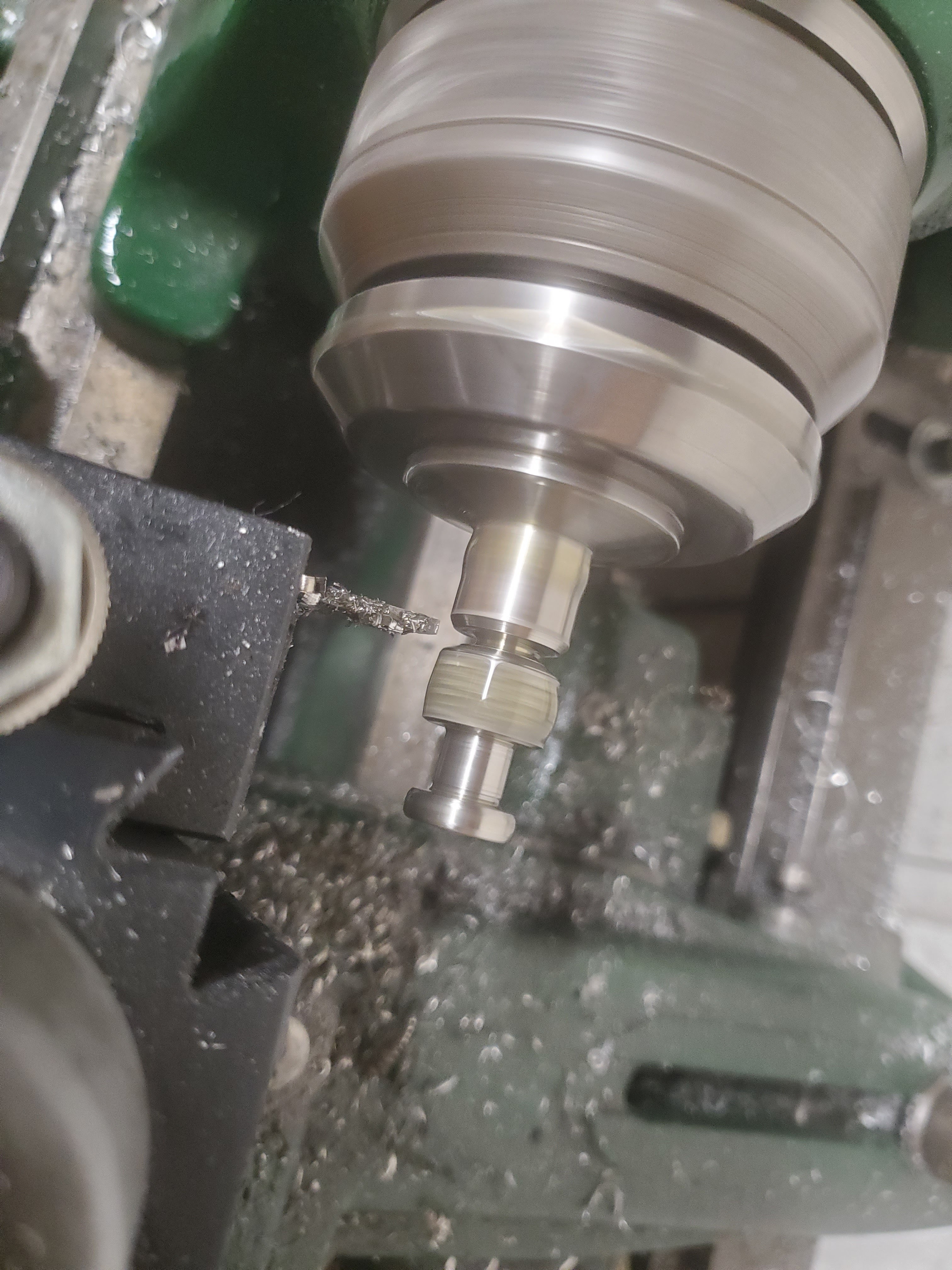
The bar was chucked into a 5C collet, and faced off.  Then, I drilled it with a #6 drill bit, which is 0.204" or (5.18mm, since this is a metric part).  As an FYI, a 5.2mm drill bit is the right size to tap aluminum.  I was even smaller, so I purely thought I could get perfect threads out of this.  I commenced tapping.

At some point, you cut your losses and give up on tapping this stupid part all the way through.  That's when I found the pre-existing part was NOT tapped all the way through, either.  When I measured to the threads, I found it was about a half inch or 12mm of thread.  I made the decision that I would stop trying to run threads at this stage, and drill for clearance later (after it was removed from the lathe so I could actually get to the back side of the hole), and then I'd hand-tap the rest of the way.

I moved on to the next step - knurling. I also took the time to do some knurling.  This was my first chance at using the scissor knurling tools, instead of the pressure knurling tools.  If you think your knurling is impossible, and you use the pressure knurling tools, just stop what you are doing and buy a scissor knurling tool.  Just do it.  You can thank me later.  Anyway, the knurl came out way better than any knurling I've ever done.

So, I finished the bosses and other dimensions.  The stainless sure is going to look good.

I parted it off.

I drilled out the back side until I had about 3/8" of thread meat left (that's 8mm, this is a metric part).  I then went outside and manually tapped this thing for another hour and a half.  This stainless is brutal!  But, I got it done.

I had to give it a fitness test, and yes, this is going to work.  I might need to do some more filing to get a perfect fit, but the reality is that this will suffice better than the original 8x1.0mm part.

You can tell which one is mine - it has the machined bevel on it (the one on the right side), so it's not a lazy casting of unidentified-origin metal.

This hand plane is now fully functional.  I might need to make a spacer for the wood handle so that it can be anchored, but at least it's usable now.

Saturday, February 12, 2022

Bandsaw Mitre Measurement Attachment - And Fence

 Someone asked if I could cut them some boards on the bandsaw.  I went to check it out, and the blade was dull.  Plus, my old wood fence for the bandsaw was warped.  And, when setting up the fence, I got tired of the mitre-to-board-via-c-clamp setup that I had.

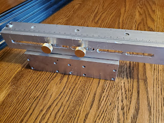
Always start with a plan.  I used some machinist gauge pins to determine the slots in the mitre gauge, and the distance between the holes.  This gave me both the distance between the two holes, and the height from the base of the mitre gauge.  Rummaging through my cut-off/drop stock, I found a bar of aluminum that would come to the height of the top of the mitre gauge, and a small, thinner bar I could cut in half to be some risers.  The mitre bar was twice as long as it needed to be, but I did not cut it - I thought this would be a good opportunity to make this attachment adjustable.  I also divided the twice-length into thirds for the risers, and marked them all out for drilling.

I planned on #10-32 for assembly, because the slots in the mitre gauge would take that size (nothing bigger).  The riser bar had two holes in it already at the ends, and that forced me to switch that side from a #10-32 to a 1/4"-20 on those particular holes.  I had thumb screws that size (in brass), so it was a natural fit to drill those for a 1/4"-20 and tap them.

A lot of drilling, tapping, and counter sinking later, I had the basic assembly.  I lost a few pictures in the mix, so I don't have photos of the simple assembly at this stage.  I needed some thumb screws to attach the assembly to the mitre gauge.  I ordered some #10-32 thumb screws in stainless steel that were 1" in length.

I used a piece of extruded, 90-degree aluminum, and drilled holes for a slot (I didn't want to break out the mill - I had too many wood tools where I'd have to go and clean up was off-putting).  The task of marking the holes took the longest.  It wasn't a single slot, and it was designed to allow overlap on the risers so that I could hit any position and length.

Once the slot holes were drilled, I used a file on the slots.  Being a soft aluminum, this went MUCH faster than the drilling.  At this point, the basic assembly was complete, but I needed a ruler.  A quick trip to the craft store ended with me having a 12" aluminum ruler that had a plastic "handle" on it.  I used a heat gun and softened the plastic enough I just popped it out of the ruler.  I then marked the holes from the ruler to my angle-aluminum, and drilled and tapped the angle (1/8" thick, #8-32 with some machines screw washers).  I had a big pile of parts.

This was assembled into the final assembly.


While here, I took two 25mmx75mm aluminum extrusions and cut them down to size.  I added angle blocks to lock them together into a bandsaw fence.  After checking for squareness, I cussed a few times because it was 0.035" out of square over 75mm - or 1/32" over 3".  Sorry for the mixed metrology there.

I cut a few 0.012" shims and stuffed them into one end on the angle brackets, and had it fully square.  Phew!


I ran both out to the bandsaw to check the fit.  The attachment dropped into the mitre gauge slots perfectly, andI ran a few tests.  It worked out perfectly!

Here's how it works.

  1. Clamp the device clamped to the mitre gauge.
  2. Position the ruler near the saw blade.
  3. Loosen the brass thumb screws holding the ruler in position, and slide until the desired depth of cut is obtained, and lock the thumbscrews to keep the ruler in position.
  4. Shift the mitre gauge to one end of the bandsaw, and slide the fence up to the ruler end.  Lightly lock that end of the fence down.
  5. Shift the mitre gauge to the opposite end of the band saw table, and repeat the sliding of the fence against the rulers, and lightly lock it down.
  6. Once more, do the opposite end that we've done already, just to make sure.
  7. Lock the fence down.
  8. Remove the miter gauge (or the attachment if you are using the mitre gauge itself for your cuts).

Then, you are set up, and ready to go.


Now, once I get time to do some re-sawing, I'm ready.

Sunday, September 26, 2021

Stool Sample

Crappy title. It is all accurate, it just doesn't end up where you think it does.  I know, and I'm sorry for misleading you.  I don't do click-bait very well.

Anyway, we're gathered here together today to celebrate the fact that I have a wood shop now.  While it's true that it has to be mobile because my wood work is done on the back porch, I actually have all of the tools - drill presses, band saw (with re-sawing blades), belt sander, jointer (or joiner, if you prefer), mitre saw, table saw, and a planer.

I need to build a table for family.  But, I absolutely have to know that what I have will do the job, and that requires a first quick-and-dirty project.  What do I have available to use?  Only 2x4's (the ones that are actually 1.5"x3.5") are available.  So, I thought I should turn a 2x4 into a little folding stool.

I had a small gardening stool (or chair) I'd made in wood shop back in junior high school.  The thickest piece of wood was 3/4" so I thought it would be an excellent project to make out of 2x4's.  It would require re-sawing the boards to get close to the 3/4" thickness, a table saw to trim seat slats off of boards, a jointer to properly square the boards up, and a mitre saw for the chair feet.  I grabbed it, and slapped together dimensions followed by a "cut list".

Looking at the list of stuff, I needed :

  • 3/4"x2"x15" (four of these) for legs
  • 3/4"x3"x11" (two of these) for the seat frame
  • 1/4"x1.5"x11" (7-10 of these) for seat slats
  • 3/4" dowels

I first ran the 2x4's through the table saw.  I needed two boards that were 3"x3/4"x11" (they are the sides of the actual seat).  These are the widest of the parts, and I needed two of them.

While I was at it, I ran another section of the 2x4 through the table saw at the same position to rip another strip the same thickness off that came from the piece for the 3" one.  On that board, I ripped it a second time, repeating the ripping while getting a little closer to 2" in dimensions for the chair legs.  Each of those thin strips that came off was destined to become part of the seat slats.

With the board widths close, I took the boards to the band saw and re-sawed the boards to about 7/8".  This allowed me to generate even more material that could be planed down for seat slats.  I finally had my boards close to dimensions (except for lengths on the legs).  Here are the three sections of 2x4's and what they were trimmed to.

I needed the thickness of the boards to be dead on, so next was to run them all through the planer.  I did start with the legs, slowly bringing them down to the 3/4" that I needed, and then turned my attention to the thin strips for seat slats.  They were about 3/8" thick, so it didn't take a lot of time to get them down to the right thickness.  3/8" thick would have actually been fine for slat thickness, but I shot for 1/4".

I ran them through the joiner to square them up (this isn't really necessary), but it gave me the dimensional lumber I was in need of - 2"x3/4" and 3"x3/4".

The next task is to mark out the other dimensions required (the lengths).  I sliced them off at the miter saw starting with the seat slats, and moving to the seat frame.  The legs needed a mitered cut at the bottom, so I did that, and then made sure all of the legs were the right length.

This little stool includes a curved frame.  This is because I don't know anyone with a flat butt, so the frame ought to be the same.

Next up was a little seat frame marking, and leg marking.  I need two holes in each leg (one for a pivot and one for an anchor), and two holes in the seat frame.  I marked all of the locations according to the dimensions I'd checked from the original.  I needed to put in some curves on the seat frames (because no one I know has a flat butt).  In the middle, I marked in 3/4" from one side (the top side), and then set the board onto the table saw.  Using string to get the radius (it was tied to the table saw fence), I moved the board until I could get close to the middle 3/4" mark and also the topside's corners, forming an arc.

Then I just used that to mark about every inch, and then connect the dots.  It's not a perfect curve, but it was close enough.  I'd only marked one side of the seat frame - you'll know why in a minute.

With everything marked, it was off to the drill press to punch out the legs and seat frames.  While there, I used a hole saw to make four small circles about 3/4" thick and 2" in diameter with a 3/4" bore.  These are "retainers".  I brought the parts back to the table saw, and used the jig saw to cut out the curve on the one seat frame.  

Next, I grabbed a dowel, and used that to line up the two seat frames.  Note that I had marked one hole on each of those seat frames about a 45 degree angle.  This is to be cut out, and both of these seat frames needed that cut out on the same side.  Then, I could draw the miserable attempt at a curved line onto the other seat frame so that the two frame tops can be parallel.

With the final cuts marked, I grabbed the jig saw again, and cut out both the arc on top of the other seat frame, plus notched those two holes.  I now had my entire cut list complete, and I was ready for assembly.

The air compressor was fired up, and I grabbed the brad nailer and tacked it all together.  Yes, there is no glue on this chair - don't let the picture above with the wood glue in the corner fool you.  Some joints are not tacked, and some are.  It allows anchoring at specific points and mobility at others.

And finally, compared to it's template (the one from junior high school) :


It looks like I am ready to try the next project, the table!

Sunday, November 22, 2020

It's Like Magic

 I love family.  Frankly, my greatest joys are family, and if not family there are some who would be close enough.  Sure, machines are awesome, but these people are a priority.  What's probably weird is that it is an antisocial guy who is making those statements.

When your niece asks you for a wand from the Harry Potter books, do you stop working on stuff and focus on that?  The answer is a resounding "yes".  My niece is a fanatic of "Luna Lovegood".  She asked me to make Luna's wand for her.  That silly niece knows that she can ask, smile, and I'd make something for her.  (The others do, too - which doesn't bode too well for me as they ALL have me wrapped around their little fingers.)

This was actually the most technically challenging thing I've ever done, and I've done some things to within five thousandths of an inch.  Turns out, this was a piece of wood done to within 5 thousandths of an inch.  Not knowing about the wand, I took to the Internet.  I found a picture of the wand and a brief write up about it (a Harry Potter fandom page), obtained the overall length from another Google search (34cm), and scaled and printed the wand.

Next I set out with calipers to get the dimensions (distance between features, diameters, etc).  That gave me a "machinists drawing" to work from.  I could not find any rosewood, all the wood shop stores had were maple blanks, so that's what I had to use - white, untainted, plain maple.

I broke out the wood lathe, and....

...promptly hosed the first one.  I learned that with that much flex, I needed to do the ends first, and work my way to the middle.  If I turned down the middle and then did the ends, there was too much flex in it and it would likely break.  I also found that you need to use a support with where you are cutting the wood - and since follower rests don't exist for wood lathe tools, you have to use your hand.

I do not recommend using gloves on a lathe.  I do NOT NOT NOT! But that's what I had to do.  Friction from the gloves and the wood got hot enough that my nerves were damaged (it still hurts typing this up and it's been a few days).  But, any sacrifice is worth it for me nieces and nephews.

I finally got a reasonable replica of the movie one (which looked like dark walnut, actually, not rosewood) in shape.


Next was indexing the grooves on it.  It was the first time I'd done indexing on the wood lathe.  It turned out okay, and I was excited to do it.

For the finishing, I used stains (I was starting with plain maple, right?).  First were two layers of "sedona red", followed by a couple of coats of dark walnut.

The final result still has yet to be done - I need to part the end off to length, and I need to cut the pommel side into the wand.  But the interim result looks fabulous!

Thursday, April 23, 2020

Another Lathe (I Have a Problem)

Please, someone might need to run an intervention.  Yes, I have picked up my 5th lathe.  You read that right, I have five of them. I have two metal lathes (A South Bend Junior 9" [nick named a "Heavy 9" from 1929], and a South Bend Heavy 10 10L from 1957), and two wood lathes (make that three).  The new one is just like my first one - a Dunlap 1942 534.0601 Sears special, and the middle one was a little tiny cute thing that came with a bunch of motors and probably will do well turning pens and other small wooden objects.  In fact, I specifically targeted the Dunlap model because I know I can use the first one for spare parts as needed, it's a really high quality cast iron, and I can also even daisy chain the Dunlaps end to end and make some rods that are longer than the 3'6" maximum it provides.

Over the last few months, I've been building the lathe stand and refinishing the new old one.  I used machine spray paint on the last Dunlap, and I don't like the results, really.  This time I am using a brush-on enamel.  Both the stand and the lathe were painted with it.  I've been doing the assembly, and aside from the motor, this lathe is ready to run.  I did have an upgrade, though.

All parts came off.  This one even includes an upgrade.  The concept came from the South Bend Heavy 10 build, where you use a roller bearing as the take up washer instead of a brass washer.  This tiny wood lathe doesn't have a takeup washer.  I purchased


With it installed, I could adjust the tightness of the spindle turn until it had an acceptable amount of play with ease of rotation.

Next, I have to figure out how to attach the motor underneath this (inside the frame).  As this will use a link belt, I'm not worried about the belt "forming" or causing too much vibration.  I started out by taking a chunk of 3" found scrap aluminum (1" wide), cut it in half, milled the flat even flatter, then milled a notch on the opposite side.  I drilled holes to bolt it to some C channel, and one big one in each side to take a 7/16-14 tap.  This would become a clamping surface for the counter shaft and motor, without altering the stands structure.

I picked up a 7/16-14 left handed tap and die, and proceeded to cut the threads into these blocks (one left hand thread, one right hand thread).  Once I had them ready to go, I used a chunk of hex rod, threw it into the lathe, and rounded off each end (had to face it).  I put a right hand thread one one end, and then puckered up for the left hand thread on the opposite end.  This was my first job at cutting a left hand thread on the lathe.  Of course, I cheated.  Once I had the thread close, I used the die to finish it off for a perfect thread every time.


With the threads cut, I could start the assembly.  With opposite threads on each side, you can turn the hex bar one direction to tighten, or turn in the opposite direction to loosen.  I put the milled ends (I'll call them "nuts") on as far as they'd go onto the hex rod.


Then I could slide the assembly into place between the bars on the lathe stand, and expand the two nuts out.

From above the lathe

From below the lathe
Once tightened in place, it was absolutely solid.  Now, I know it will work.  I can build the bar next to hold the jack shaft bearings, and then put the counter shaft in place.  Once I had that, I could install the countershaft and motor.  While I was at it, I installed two aluminum bars across one side that was about the same as the bed gap, and on that I put the old lathes milling attachment, spare tool support, and the old tailstock.  The old bed was bolted to the back of the stand, and the headstock underneath the bed.  With the castors in place, I can easily raise the lathe off of the ground and onto castors, move it, and then drop it back down.  It's effectively stable in either fashion (I tried to do the weight distribution in a way that would work).


I have yet to attach pegboard on the tailstock end for the wrenches, screwdrivers, sandpaper, and turning tools, but it's operational and ready to use right now.


I'm stoked to remove the old bench and put this one in it's place!