Friday, December 28, 2018

Heavy 10 Headstock... Fits A Junior Bed

I had an impression that this would work, but finally knuckled under.  I ordered an old Heavy 10 (South Bend lathe) headstock off of eBay to see if it would fit onto the 9" junior bed. The first thing I did was take a picture.  Then I measured it's base :


Note that those measurements are relative to each other.  Then I measured the Junior's bed :


After that, I set it onto the lathe, with success :


Note that although it fits, this headstock is an under drive, and my lathe bed is an overdrive.  That means this won't work.  [sigh].  Now that means I really need to get a heavy 10 bed (on it's way here), tailstock, and carriage.  It also means I need to start buying parts to get the headstock into an operational mode.  My new toy has an expensive shopping list:


  • oilers (felts and gits)
  • thrust bearings
  • take up bearings
  • take up nuts
  • spindle gear
  • spindle bull gear
  • spindle headstock bearings
  • bushings
  • forward/reverse gear mechanism
  • back gears (14DP, 70 tooth on the bull back)
  • gearbox
  • banjo and idler gear
  • lead screw gear
  • saddle apron
  • cross slide
  • compound slide
  • tailstock
I might be able to manufacture a few parts with my junior, but it would probably be simpler to just buy them.

Sunday, October 28, 2018

Shortening a Fly Fishing Rod

My wife is an avid fly fisherwoman.  I wanted to join her, so I ordered a fly rod and reel off of amazon.com, and when it arrived, I had a distinct worry.  I do love the outdoors, and backpacking, so I had ordered a 9' rod that came in 4 sections.  When I assembled the rod, it seemed way too long for some of the places I have hiked to (tight corners in the streams, lots of overgrowth and trees covering the waterway).  I wanted to be able to hike with a 9' for lake-side fishing, but shorten the rod in a pinch for other places.

Maybe I simply thought that this was a good excuse to head out to the shop.

Either way, that's what I did.  I had a chunk of 1/2' aluminum rod from Home Depot from a previous task, so I chucked it up in the lathe and turned it down to an outside diameter 1/8" larger than the ferule side of the butt-end of the rod.  Then I turned down one side of it to the outside diameter of the next section (which has a taper, BTW), and then drilled it out to fit over the butt-end, ferule-side.  Essentially, it's a lightweight part that eliminates the section of rod that connects to the butt-end, and it fits in the cap of the case.


Granted, it DOES change the speed of the rod.  The rod becomes much more stiff down low (which means the rod becomes "fast").  The purpose was not to have two moderate rods of different lengths, it was to have a single rod that could work in a pinch for a different situation.  You simply have to change your casting method.  It fits, it is extremely light, and now I can pop into odd situations and still spend a day doing nothing (like that's going to happen).  I finished the rod up (and also my wife's rod), and I'm ready to go!


Now I just need to set up a time and go on a fishing date with that hot wife o' mine!

Sunday, September 30, 2018

Tailstock Die Holder

For all of those wonderful times when you want to thread, but you are too lazy to switch change gears for the right thread pitch, I give you my version of a tailstock die holder.  Essentially, it is a thread-cutting tool to sit in the tailstock.


Mine was made using 5/8 tool steel road that was drilled for a 3/8-24 thread in one end, and screwed onto an MT2 arbor that was 3/8-24 on it.  Then, a cylindrical piece of aluminum was cut, turned, faced, and bored out, and then some set screw holes put in it.


Mine had a 1.5" hole bored, as well as a 1" hole.  Then, I can use two different types of dies.  Also, it was turned to a 2" diameter so I can use a 2" inner diameter tube and hold a 2" die, too.  It means I can hold the vast majority of dies for easy threading on the lathe!

Sunday, September 23, 2018

Starting RMAV (Remotely Manned Arial Vehicle)

I'd wanted to build a quad-copter.  Out of curiosity, I found a carbon fiber frame on a Chinese website for $30, and I ordered it.  I took it into the office (we have a guy that loves anything RC), and he talked about it being just like the one he paid $100 for.  After realizing I had a Chinese knock-off, I decided to keep building.  I'd like to buy one of those $100 frames just so the guy gets credit, but that will come when my wife thinks FPV is cool and takes over mine.  The gentleman that designed and built the kit is known by the moniker "Ummagawd" and is involved with Rotor Riot.

QUICK NOTE - Buy the $100 frames.  After having to break out the dremel with the grinding wheels to clear some space for the receiver and the video transmitter and getting carbon fiber all over the place, I'd strongly suggest getting the good frame that has pockets designed for that.  Still, this little project got me started into building a drone.

Anyway, here we go for a quick parts list :


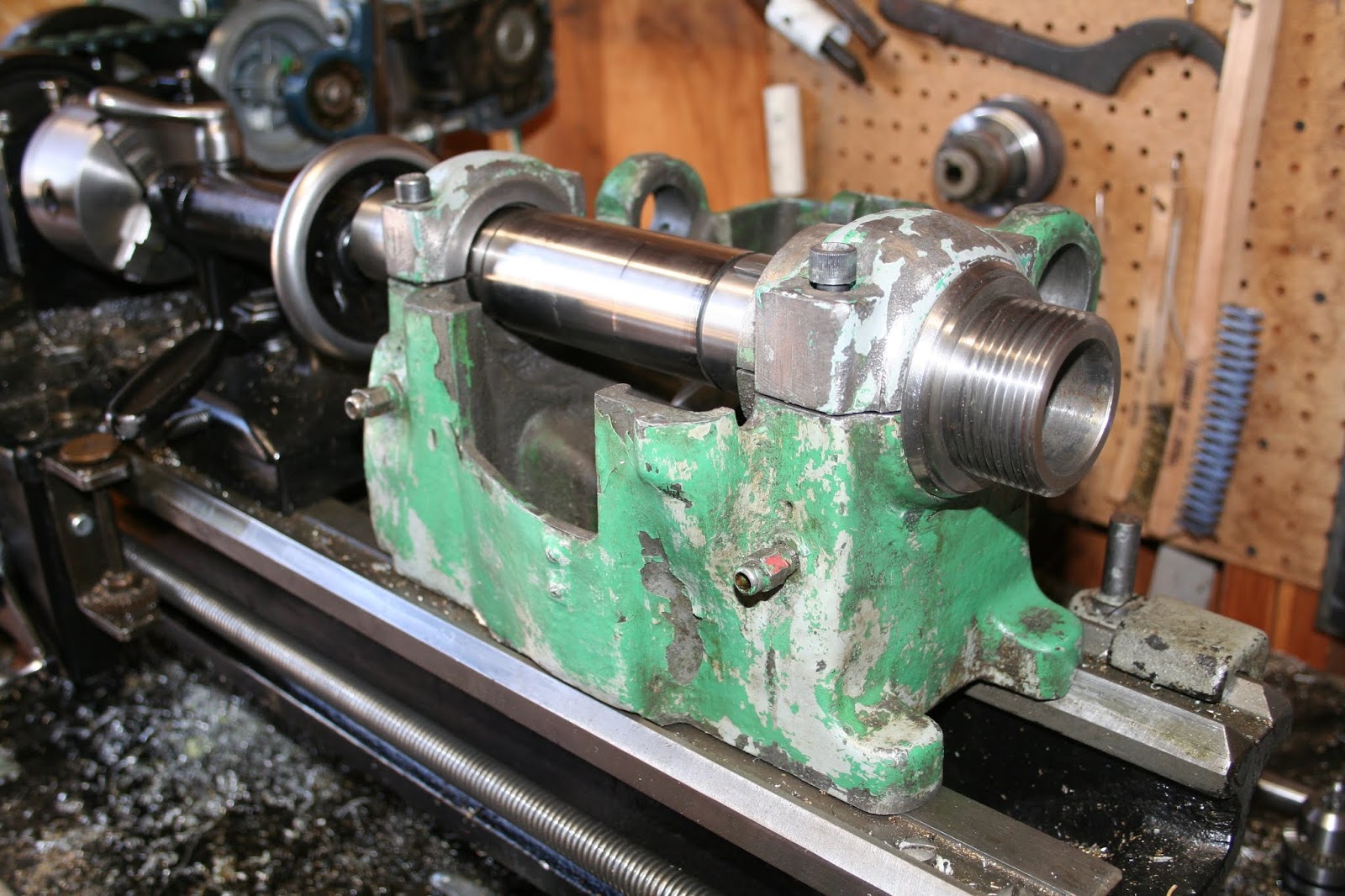
I think green is cool.  So, I ordered green tubes (I needed 34mm and a 28mm tubes) and green cone washers.  The 34mm tubes didn't come in the size required for the quad frame, so I needed to turn them from 35mm down to 34mm down on the lathe.  Being cheap aluminum, the first one bent.  I chucked up the second one closer to the collet, and was successful :


My quad now has KV2600 T-Motors in green.  Since then, I've added the flight stack, and added some heat shrink tubing to secure the motor wires to the arms.  I've also added green antenna tubes in order to get a little more complete.  My propellers are a 3-blade HQ with a pitch of 4.3.  I know they sell 4.8 for quick response, but I'd like something a tad bit more gentle.


The above picture was taken before the green lock nuts arrived.  As of October 28, 2018, I have picked up an orange RunCam Swift 2 camera, and I removed the case and painted it some random color.


After painting the camera body, I installed it, and then realized I did not like the running of the antenna tubes.  I re-ran them along the front arms and left them relatively straight to increase the signal reception.  This gave me a little cleaner look as well (a nice side effect) :


Additionally, I have finally picked up the following, and I am preparing to install them.  On the left is the Spectrum SPM4648 DSMX receiver.  In the middle is the Lumenier AXII 5.8Ghz U.FL RHCP antenna for the video transmitter.  On the right is the ImmersionRC Tramp HV 5.8Ghz video transmitter.  On the bottom is the Spectrum SPM USB Simulator (so I can fly the quad without flying it using the ImmersionRC flight simulator).


Along with the Spectrum DX6, all I need is a battery, a charger, and some optional Fat Shark dominators for the first person view.


Progress is slow, but is coming along nicely.  I took the frame apart to start clearing out the area for the receiver and the video transmitter.  Note, it is worth it to simply get the pricier frame from Ummagawd because it has all of this cut out and in place.


Once that was cleared out, it was time to start re-assembling everything.  I'm using the HobbyWing XRotor series of flight stacks (F4 G2) :


Make sure when you install it that the arrow by the battery soldering pads points toward the camera (this is the "front" of the quad).  Next is to solder the cable to the controller that connects to the receiver.  For the Spectrum receiver (again, SPM4648), there are three wires from the connector.  Black should get soldered to the ground spot on the controller, the orange goes to 3.3v (do NOT do 5v).  And the gray should be soldered to the Rx spot right next to the orange cable.  Don't use the SBUS unless you are using an SBUS receiver.  Each receiver behaves differently.  The Rx are received UART connections (think of your old modems).  The Tx ports are for sending data to something else (e.g. an additional transmitter).


Next, I need to solder the motors to the controller, slide the receiver into position and install the flight controller, and the battery connector cable.  After that was soldering the receiver wires to the board :


Set up the antenna (remove the pigtail on there, clip the new antenna into place, and use hot glue to seal it up and keep it in place) :


Get the wires into position for all of the cables (including the transmitter we just hot glued) :


Make sure everything fits before closing it up.  Use enough Loctite to keep it from coming apart mid-flight on you.


The completed hardware quad :


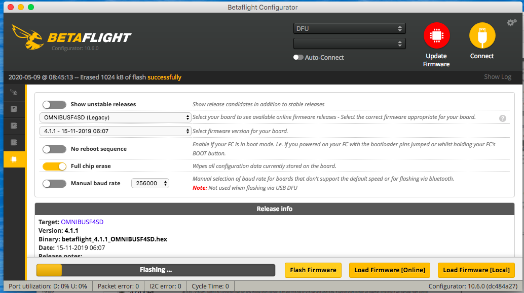
When I finally picked up the battery and charger, it was time to start the programming.  For the flight control software, use BetaFlight, and the firmware to use is "Omnibus F4".  If you have an option for "Legacy" or something else, I'm not sure it matters.  I chose the "Omnibus F4 (Legacy)" firmware and it works great.  Here's the screen shots of the firmware update :


The original designer of the remix produced a youtube video in conjunction with Rotor Riot in which he runs through the entire build, including some quick steps in BetaFlight.  This is a must-see.  In it, he encounters motors in the wrong location - don't be surprised, I would be more surprised if it came out perfect the first time.  Mine were out.  Using the BetaFlight CLI, you will need to "get resource".  This will dump a lot of information to the screen.  Copy this to a text file somewhere.  There are four motor lines you are interested in :
    resource MOTOR 1 B00
    resource MOTOR 2 B01
    resource MOTOR 3 A03
    resource MOTOR 4 A02
    
To switch motor locations, I'd suggest pasting the MOTOR chunks twice (one for reference).  You are going to change the motors out to where they should be.  For example, I had all four motors backwards because I did a calibration that Ummagawd didn't do, and it right-sided the quad for me.  With all motors being changed, it ended up like this :


And, so you don't have to translate that, the text for the commands looked like :
    resource MOTOR 1 none
    resource MOTOR 2 none
    resource MOTOR 3 none
    resource MOTOR 4 none
    resource MOTOR 1 A03
    resource MOTOR 2 A02
    resource MOTOR 3 B00
    resource MOTOR 4 B01
    
Wait a minute!  What are those "none" lines?  Oh, yeah, before you can assign the new motor settings, you have to free those resources.  THAT"s what that is about.  You can then copy the code into the CLI, and press enter.  It should prepare the changes.  Once done, you can then type "save" and press enter.  The quad should reboot, and you can re-test the motors.  All should be well.


Following along, I had two motors that would not turn the proper direction.  In the above screen shot, on the motors tab, you see the directions they are supposed to be turning.  Ummagawd used a program called "BLHeli" to change direction of two motors.  In my case, BLHeli would not connect to the ESC's (you could try it if you'd like, here's another youtube video using it), so I could not reverse two motors (they were different from the ones Ummagawd found in his above-linked video).  Before throwing in the towel and scrapping your project, you should understand that you can take any two wires from the motor, and switch them.  This will reverse the motor.  Find the motors that need to be reversed, and mark them some how (e.g. some tape).  Then move to the soldering station, switch the wires around, let things cool, and test it again.  It should be solid.

Now, I struggled to bind the quad to my receiver.  Since I had opted for the Spectrum SPM4648 receiver (DSMX), I deviated from Ummagawd's list of supplies, and it cost me a day of poking things until I found something that worked.  It was stupid, really, what caused me so much consternation, but here are your settings.
  1. In the ports area, enable the "Serial Rx" on the proper serial port you soldered the SPM4648 to (should be UART3-Rx, since that is less likely to have voltage inversion settings on it).  Save and reboot.  Reconnect as necessary.
  2. In the configuration tab, under the "Receiver" section, set the Receiver Mode to "Serial-based receiver ("SPEKSAT, SBUS...").  This shows another drop down for "Serial Receiver Provider".  Set this to "SPEKTRUM2048/SRXL".  Click "Save and reboot".  Reconnect as necessary.
  3. Swtch to the "Receiver" option (the one that looks like a transmitter).  On the "channel map", set it to "TAER1234".  If that doesn't show up, one of the options should have "SPEKTRUM" in it.  Select that and click "save" at the bottom.
  4. In the CLI, set :
      set spektrum_sat_bind = 9
    Then type "save" and press enter. The quad should reboot, reconnect as necessary.
  5. If you run through the process and it has problems binding, you may also need to run the following from the CLI (remember to "save" when done):
      set spektrum_sat_bind_autoreset = ON
  6. Bind the receiver to the transmitter.
  7. If you had to set spektrum_sat_bind_autoreset to "OFF", please turn it back to "ON", or you could forever find yourself re-binding every time it booted. Don't forget the "save".
Once you have bound the transmitter and the receiver, re-connect betaflight to your quad.  Locate the receiver option again, and flip the switch you want for arming the quad.  You should see one of the AUX connections change values.  Make a note of this.  You can move to the "modes" section and set that up.

Once you have it the way you want it, save the options, and give it a test.

Wednesday, August 22, 2018

When Your Truck is Missing Parts?

Last week, someone was stopped aside the freeway with emergency flashers.  The last thing I wanted to do was to get to work, so I stopped to help.  I quickly found out that the individual could not get their jack underneath the car (hint: don't lower your cars, folks).  I finagled the jack underneath, and lifted the car.

Then we found out they didn't have a lug wrench.

So I headed back to my new-to-me truck to see if I could find mine.  I'd only had the truck for a half month, so this was something I needed to learn.  And that's when the new realization hit me ....

I didn't have a lug wrench or a jack for the truck!

I didn't even have the bracket that holds the jack and wrench down.  It typically sits underneath the front passengers' seat, but where it was was a threaded hole that would allow water to permeate the interior.  Not good.

So, a quick call to a dealership, and they can't even find a part number to order.  A check to eBay, and someone out there is charging $120 for the assembly.  I fired off an offer that was rejected.  Rather than face up to a low-ball and buy it, I grabbed parts from Home Depot, picked up my spare Kydex sheets, and bought a bottle jack from Harbor Freight.  Then it was a matter of assembling a frame.  I heated the Kydex and formed it around the jack (I didn't want a potential hydraulic fluid leak), and then riveted the thing together.


I did have to trim a panel to get it to fit, but unless you know what you are looking for, you'll never see it.


The other thing was that I didn't have a 6mmx1.0 hold-down bolt, so I turned some 1/4" threaded rod to the outside diameter and used a metric die to cut it, coated it with Loctite, and created my own hold down bolt.


Not bad!

Wednesday, July 4, 2018

Bullet Ear Buds

At one point, I had made a pair of these (not my video) :


But, since I use them most when traveling on aircraft, I wanted some that worked a little better with not-so-short wires, but that could make it through TSA without being confiscated due to the gun powder residue.

This resulted in a little different approach.  Here's what went into these :


  • Unused and unloaded .40 caliber brass cartridges, nickel plated
  • TDK EB760 Ear Buds for the drivers
  • A cheap pair of braided-wire ear buds from china (the color I wanted), primarily because the TDK wires are too short for me, even before cutting them out
  • A small chunk of round aluminum about a half inch in diameter
Tools used :
  • A cheap harbor freight heat gun
  • A small tool vise
  • Soldering iron
  • Small, round file
  • Drill bit just larger than the to0be-used speaker wire
  • My metal lathe with some collets (you can use a drill as shown in the video, but my experience was better with the lathe as explained later)

Once I had everything, I started by using the lathe to cut a brass plug that would press into the primer spot in the cartridge casing.  It was about 0.172 in diameter and pressed into it perfectly (make sure it's the right side when cutting the fake primer).

Place the casings into the small tool vise, take them over to the drill press, and (using the drill bit just larger than the wires) punch a hole in the side of the casing as shown in the video.  Use a counter sink to remove the raised edges and clean it up.  Do this for the other casing as well.

Next, I measured about 12mm in length from the back of the casing.  I need the line as I will put the casing into a collet with the primer side in the collet to both protect it during the cut, and also allow me to clean it up after the cut.  Make that cut, then bevel the outside edge.  Using a small, round file with a handle bevel the inside edge of the casing as well.  Because we are using un-spent brass, there is no expansion, which results in the casings being a little too snug in comparison to what is in the video, so we absolutely need a centering bevel on the inside.

Using the heat gun, heat all around the TDK ear buds until they come apart.  Don't get them too hot or you could destroy the drivers, and that is what we need out of them.  Once they come apart, cut the wire to release the speaker driver and the casing that holds it (and the rubber/silicone things that hold them in your ears).  The driver and the casing the driver sit in are what you want.

You now need the wire from the other ear buds.  Cut them free from the cheap ones, and then push the wire through the small hole from the outside of the casings to the inside.  Tie a knot to prevent them from coming out.

Use a soldering iron, release the old speaker wire still attached to the drivers, and attach the new wire that was fed through the casing side.  You may need to clear insulation on the new wire until you get to the colored speaker wire on the inside.  Solder them up like the old wires were (colored wire to colored pad, copper wire to the other pad).

Finally, I crushed the driver housing when I tried to press the housing into the un-spent brass.  I ended up using the small aluminum round after drilling a hole through it about a 0.25" in diameter, and them putting a concave surface.  I then took that with the driver housing and casing back to the small tool vice.  The round went over the top of the driver housing so I could press on the sides of the driver housing rather than the front, then centered everything up, and pressed them together.


I put the silicone parts back on, and tested them out.  They are pretty slick and pretty nice!  Great sound, cool look, and I HOPE it should get through TSA without confiscation.  Note, I have not yet tried to get these through TSA, so I don't know if they'll make it through.  I certainly hope they will.

Sunday, June 24, 2018

Milling Stand and Ball Turning Attachment

I had a brief moment to work on some "projects", so I took that and ran with it.  First up was a ball turning attachment for the lathe.  I picked up some 5" x 12" x 5/8" steel plate, and drew up the fork on it.  Then I drilled a few holes to make turning corners in the bandsaw a little easier :


Once that was complete, I drilled along the swing arm on the inside (the blade wouldn't be able to make that turn, even with a drilled hole), and then cut along the lines.  I simply used a hammer to break out the inside chunk since I drilled along the base line of it.  Before freeing the entire pieces, I drilled sideways (which will become vertical when complete) to ensure that the pivot points are lined up.  You will see that in the second picture :


Then, the final cut along the hilt where it will sit in the tool post holder to free it all up.  Here is an exploded view of where everything ended up in the plate steel :


The "forks" were still a little rough :


At that point, I used a flap disc on the angle grinder and the milling machine to clean things up.  My biggest worry was making sure the drilled holes when expanded remained on the same axis.  If the top axis was even slightly not lined up with the bottom axis, it won't pivot very easily.  This meant that I MUST drill the final holes in line with the other end.  A drill press won't cut it because it wouldn't guarantee that the axis' would be parallel.  So, I used the live center to keep the points lined up, and a drill bit in a collet.  This allowed me to swap sides, and drill them out.  I did both the frame and the c-channel that pivots.  The large channel was drilled with 3/8" (0.375"), and the c-channel was drilled with a 1/4" (0.250").  On the c-channel, because it was smaller than the swing, I had to use a board between the ways to keep it solid.


Once done, I verified that I could put a 3/8" rod through the holes (meaning they were parallel).  Perfect!


I then had to cut some bushings.  They were first turned down (with a flange) to a minor outside diameter of 0.375" to match the holes.  I drilled them to 0.250" to match the sizes of holes in the c-channel holes.


I pressed the bushings into the frame.


Then, to make sure the whole thing would work properly, I grabbed a 0.250" (1/4") rod and placed it through all of the holes, and ensured that everything turned properly.


The next steps are to broach the tool holder in the c-channel/swing arm (you can see it in the picture above) into a square hole, cut some flats on the 0.250" rod and install some set screws for the rods and tools.  After that, a simple handle and we're good to go!


Notice the square broach.  I built a broach out of 7mm HSS.  Being a stupid idiot, I first tried turning it on a lathe.  That is a bad idea - it will break your carbide tooling, and does nothing to the square.  Next, I used a grinder to make it "round" and cut "reliefs" in it.  This did nothing more than get it jammed into the round hole.  So, I used files to make the hole a little more square, then fed a 6mm HSS blank through it (squared up the hole to 6mm, still less than the 1/4" I wanted for tooling).  So, I then fed the 7mm "rounded" broach.  I was puckered up a little, but I ended up with a square hole.  I then locked it onto my mill, cut a flat, and then drilled a hole for a set screw.  Another note, I didn't see many options for a #12 set screw, so I had to go up to a 1/4" set screw.


After tapping that, I took all thread, and put a bend in it using heat and a press, then put it all together.  All I need now is an XL tool holder for the AXA, and I can tell everyone I have balls of steel!


Speaking of the milling machine, I also built a stand, since it is heavy and I don't like moving it around.  I also have limited space on tool storage, so I had to make it "mobile".  Turned out okay :