

With the latest wood shop tool acquisition (and preparing to build a table), and without a large shop I can use for either wood work or metal work, I have to have mobile tools that I can throw onto a shelf when not in use.
For this tool stand, I'd usually make a few cuts on the legs to bend an angle so I can get a good footprint (stable stance - like the wood lathe stand, the heavy 10 stand, or my mobile mini-mill stand). This time, I opted to try to simply bend the metal, but that required making a bending die. I had made the bending tool a few years back, but I can't bolt that to anything stable enough to use it, so I'll opt to use the hydraulic press. It means I need a jig. I cut the steel for the stand (I'm using 3/4" square tubing that is 1/8" thick, so it should be solid enough for any tool I throw at it.
After setting up for the bend, I went to make the actual bending die for the press. As I was turning it on the lathe, the countershaft bearing went out.

This forced me to put everything on hold while waiting for new bearings. Once I had the lathe up and running, I finished turning the die. I only cut the groove 1/2" because the outside curve probably won't buckle as much (not compressing that one). The bending die was then slapped into the bandsaw and sliced in half.


With the bending dies, I now had the tools I needed to progress (yeah, the lathe to make the tool to make the legs for the tool stand so I can use a tool - hmmmmph!). This nested tool loop is expensive. Anyway, back to the legs.


Obviously, that's not the final shape, but it let me know where to start welding first. I started on the long sides. The 16 degree bends I wanted vertical, so a little math, and I could stack a few blocks together in order to establish angles that I wanted for everything.

It was a repeated process of weld-this, fail-to-get-penetration, cuss, clean, re-weld, un-tangle-mig-wire-jam, good-weld. I think my wife laughed at me - a lot. Anyway, once it was welded up (no stack of dimes, here - I go for loose dimes in a change drawer), I welded some nuts into the feet so I can put some bolts in, or thread in rollers for moving the tools around. I didn't want to do anything fancy. P.S., don't use zinc-plated bolts when welding if you have other options - you'll end up with headaches and nose bleeds from inhaling airborne zinc.
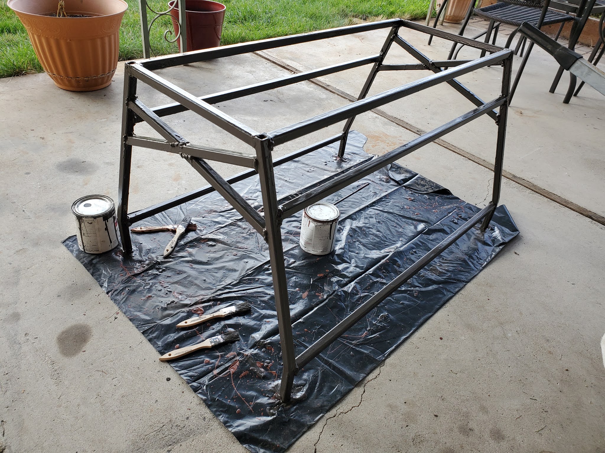
When you see the next picture, you might wonder why I didn't add stretchers on the short sides at the bottom. This stand was specifically designed to slide over the unused Chevy 350 corvette motor sitting to the side to take up no more space than I am already taking up. The higher-up stretches were more painful to do, but it should still provide enough operational strength to be satisfactory. A little grinding and paint is all it takes to make a welder look like what he ain't.
I used a rust-oleum oil-based paint for this one - "hammered bronze". I had some left over from the Heavy 10 stand (I'd have used the aluminum silver, but I didn't want to dig through the stack of paint cans buried behind my old 9" junior lathe parts pile).
I let the paint dry, and then ran a tap through those welded nuts just to make sure all was well on them (3/8"-16). Then, I put castors on the bottom, and if I need to, I can replace those with bolts and I instantly have leveling feet.
I used some plywood I had laying around that wasn't long enough, and I glued them together for a top. It was 3/4" ply, so I ended up with 1.5" of table top. I installed the counter shaft and the motor mounts, and drilled through the top with a hole saw for the belts to pass through. As each tool is mounted to this table, I will probably have to drill for each belt, and also install pulleys to the countershaft for the specific tools. At this point, I have my first functional jointer:


It wasn't in it's final place, though. I wanted to install multiple tools and have the work-height of each one be at the same height. So, off I set to use the tool to make the wooden short stands that fit on top. I don't care how "pretty" they are, I just need them functional. The jointer stand needed a gap on the one side for the pulley, and it's weight sites squarely on the ends (it has feet), so I designed it in a way that it is easily done. (This is the bottom side of the short stand.)

The planer was done next, and it needed feet to match the body, but added surface on the outboard so that it could cover in and out feeds, plus have an out feed table bolted up for longer pieces of work. Again, this is the bottom side of the short stand that will sit on top of the tool stand.

Then I set to work on the table saw. This one is not complete, as it will require an added horizontal set up because it has no way to drive the pulley from underneath.
I still need short stands for the mitre and the scroll saws.
I need new belting for the 3/8" pulley, and one counter shaft for the table saw, and I should be able to bolt things together and use individual tools as needed.

Now I can start working on the table.