

I know I need change gears. They are rare. So, I finally knuckled under and made another purchase for $200 - the Lionel Labs "HobbyMelter Furnace Kit". I'll have to purchase refractory and install it, but this will allow me to potentially make any gears I need. Woohoo!
http://www.backyardmetalcasting.com/hmkit.html
Lionel Labs - this guy is a genius for the stuff he has completed. I've been an avid follower, and I've been fairly sad to not really see an update for a number of years - but his work and examples have been amazing and great!
Tuesday, December 15, 2015
Gearing for my South Bend Junior Lathe
The Formula
Diametral Pitch Calculator
Calculating Gearing for a Specific Threads-Per-Inch
Calculate Threads-Per-Inch from Two Gears
I finally had an opportunity to look at some measurements for change gears. I knew I needed to - I had seen multiple types of gears for things labeled "original South Bend". Some were 18DP (diametral pitch), while rare ones were 16DP. Some had 9/16" bores, while some had 5/8" bores. The 16DP 5/8" bore change gear sets are rare on eBay (I've been watching, just in case). There were some 18DP 5/8" bore gear sets, and 18DP 9/16" bore gear sets, but I have yet to see a set of 16DP 5/8" bore sets since I have had the lathe.
Rumors abound that my lathe was the 5/8" bore 16DP gears. I believe in the mid 1930's, they started moving to the 18DP gears, and then changed the bore at the end of the 1930's when they introduced the "workshop" and "toolroom" models.
I knew I needed to make sure, just in case I saw them, so that I could buy them the spot.
So, I had to grab some measurements. I needed to identify the diametral pitch of the gear. You do this by obtaining the number of teeth on the gear, and the diameter of the outside edge (where the teeth get to, not the bottom of the teeth). The stud gear that drives the idler gear is 1 and 1/8" across, and there are 16 teeth on it. The bore is (indeed) 5/8". The formula is :
This gave me :
And that resulted in a 16DP gear. Now, when it comes to gears, there are a whole lot of equations. However, one other field that is required is called the pressure angle. Fortunately, I believe South Bend only made 16DP gears in the standard 14.5 degree pressure angle, so that tells me exactly what I need to know :
Now I just need to buy the set when the rare show up, or cut my own. I did find out how to determine the pitch based on the gearing, using an old threading chart :

Here's the formula, spot checked all over that threading chart :
For example :
As a result, you can create a new pitch not listed (e.g. a metric pitch) by plugging in a few numbers until you get rounded numbers, e.g. a 39 threads-per-inch would be :
So, if I wanted to cut 39 TPI, I'd slap a 16-tooth gear on the stud, and a 78-tooth gear on the lead screw. Isn't math, science, and engineering fun? FYI, I threw it into a fast chunk of perl to find that 39TPI, just for kicks :
I also threw the above code into some javascript to see if I could do this in the blog, and it does work :
Calculating Gearing for a Specific Threads-Per-Inch
Yes, I am editing this blog post - because I thought, "If my dad asks if I can cut a screw for him on his old car, can I calculate the gears to make it happen?" That blossomed into the desire to add a calculator for what gears would be needed on the web, specific to the South Bend Junior.
Calculate Threads-Per-Inch from Two Gears
While I was at it, I thought I'd throw one more calculator onto the post - one to get the threads-per-inch when given two gears. And something to take two gears and calculate the TPI.
Diametral Pitch Calculator
Calculating Gearing for a Specific Threads-Per-Inch
Calculate Threads-Per-Inch from Two Gears
I finally had an opportunity to look at some measurements for change gears. I knew I needed to - I had seen multiple types of gears for things labeled "original South Bend". Some were 18DP (diametral pitch), while rare ones were 16DP. Some had 9/16" bores, while some had 5/8" bores. The 16DP 5/8" bore change gear sets are rare on eBay (I've been watching, just in case). There were some 18DP 5/8" bore gear sets, and 18DP 9/16" bore gear sets, but I have yet to see a set of 16DP 5/8" bore sets since I have had the lathe.
Rumors abound that my lathe was the 5/8" bore 16DP gears. I believe in the mid 1930's, they started moving to the 18DP gears, and then changed the bore at the end of the 1930's when they introduced the "workshop" and "toolroom" models.
I knew I needed to make sure, just in case I saw them, so that I could buy them the spot.
So, I had to grab some measurements. I needed to identify the diametral pitch of the gear. You do this by obtaining the number of teeth on the gear, and the diameter of the outside edge (where the teeth get to, not the bottom of the teeth). The stud gear that drives the idler gear is 1 and 1/8" across, and there are 16 teeth on it. The bore is (indeed) 5/8". The formula is :
| Diametral Pitch = | (Number of Teeth + 2) |
| Diameter of gear in inches |
This gave me :
| Diametral Pitch = | (16 + 2) |
| 1.125 |
And that resulted in a 16DP gear. Now, when it comes to gears, there are a whole lot of equations. However, one other field that is required is called the pressure angle. Fortunately, I believe South Bend only made 16DP gears in the standard 14.5 degree pressure angle, so that tells me exactly what I need to know :
| Diametral Pitch : | 16 |
| Teeth : | 16 |
| Diameter : | 1.125 |
| Bore : | 5/8" |
| Pressure Angle : | 14.5 |
Now I just need to buy the set when the rare show up, or cut my own. I did find out how to determine the pitch based on the gearing, using an old threading chart :

Here's the formula, spot checked all over that threading chart :
| Thread Pitch = | screw gear teeth | * 8 |
| stud gear teeth |
For example :
| 30 = | 60 | * 8 |
| 16 |
As a result, you can create a new pitch not listed (e.g. a metric pitch) by plugging in a few numbers until you get rounded numbers, e.g. a 39 threads-per-inch would be :
| 39 = | 78 | * 8 |
| 16 |
So, if I wanted to cut 39 TPI, I'd slap a 16-tooth gear on the stud, and a 78-tooth gear on the lead screw. Isn't math, science, and engineering fun? FYI, I threw it into a fast chunk of perl to find that 39TPI, just for kicks :
my $tpi = 39;
my @try_first = (64, 32, 16, 20, 44, 48, 72, 56, 40, 80, 72, 52);
my $stud_gear = undef;
my $screw_gear = undef;
my @stud_gears = @try_first;
my $gear = 16;
while (!defined($screw_gear) && (!defined($stud_gear))) {
  my $stud = shift(@stud_gears);
  if (!defined($stud)) {
    $stud = $gear;
    $gear++;
    if ($gear > 80) {
      $screw_gear = -1;
      $stud_gear = -1;
    };
  };
  my $screw = ($tpi / 8) * $stud;
  if (int($screw) == $screw) {
    print "screw = $screw, stud = $stud = $tpi TPI\n";
  };
};
I also threw the above code into some javascript to see if I could do this in the blog, and it does work :
Calculating Gearing for a Specific Threads-Per-Inch
Yes, I am editing this blog post - because I thought, "If my dad asks if I can cut a screw for him on his old car, can I calculate the gears to make it happen?" That blossomed into the desire to add a calculator for what gears would be needed on the web, specific to the South Bend Junior.
Calculate Threads-Per-Inch from Two Gears
While I was at it, I thought I'd throw one more calculator onto the post - one to get the threads-per-inch when given two gears. And something to take two gears and calculate the TPI.
Thursday, December 10, 2015
Test Run - Brazing Lathe Back Gear Handle
When taking apart the headstock, I finally noticed two big issues :

- The bull back gear had a tooth that was missing
- The handle had broken off
To "fix", I could simply watch eBay for items to come up that would match an original 9" Junior lathe. Standard 9" South Bends (models A/B/C) would not fit - trust me, I found one on eBay for $20, ordered it, and (when I received it) found the bore through the handle to be offset, and about 1.5 times the size of the original "Junior".
Here's what this means. I have to fix it, or wait. The parts are slow to come by - they are a tad bit rare. I have a second lathe, and had a welder repair a crack in the bed - he brazed it. So, I thought, "I might as well try it."
I slapped a 2x4 into the wood lathe, and turned down a brace to hold the "newer" model handle. I didn't want metal, because to would end up being brazed into the handle. It fit great. I grabbed some brazing bronze rods from home depot, took them home, and slapped the part into the oven to pre-heat it. After a half hour, I pulled it out, pressed it onto the wood brace, and fired up the small torch to get it red hot.
After about 40 minutes, I knew it wasn't going to work. Turns out, when I fired up the "small torch", it was too small. By the time the handle got warm enough, the wood I wanted to use as the drill marker for the new hole was burnt. I've tracked my cutting/welding torch down, but I need regulators, hoses, and (hrmmm) acetylene and oxygen. I have tanks for them with the MIG welder, but they're empty.

So, I bit the dust on that try. I happened to find one on eBay after this attempt, so I bought it. That doesn't mean I won't try this again. Shoot, I believe I can make a temporary handle out of a bushing and a bolt (drill a hole for the taper pin, and drill a hole half-way through, thread it, and throw a bolt in to use as a handle), so using this handle isn't necessary. I'd at least like to repair the gears so that I have a back up. If one tooth can break on the gearing, I expect I can easily break another one.
Monday, December 7, 2015
South Bend - To Be Done
As I've tackled the South Bend 22YB "Junior" lathe, I've found a few things wrong. Inside the spindle bushings, I found some small grooves in the spindle :


Also, the handle had broken off on the back gear, as well as a missing tooth on the "bull" back gear. I'll try to braze fill a "tooth", and I picked up a handle for a "workshop" 9 back gear. The handle doesn't fit (hole too big), but if I'm brazing it, I might as well fill the hole in that handle and use it anyway. That's my next focus.
Plus, I need to identify a clamp - I'm not sure where this one goes :


We'll see what happens!
Thursday, November 19, 2015
New South Bend 9"x19" Lathe
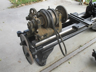
Just picked up a new toy, a South Bend 9"x19" (the 19" is between centers, not the whole bed length). Someone had already started to rebuild it, and I picked it up for a song, but in pieces :

You will notice that I've already put the tailstock back together, and I've taken apart the cross-slide and compound. In fact, the compound assembly isn't even in the picture because it's being warmed up in the house in preparation for paint. The cross-slide went back in after taking the picture.
It is true that there is no associated countershaft - the previous owner to the last owner lost it, along with the change gears. I do need change gears, but I should be able to work without the countershaft by using a variable-speed DC motor.
I found the serial number in the usual place (tailstock end of the bed) :

The serial number found on the lathe bed is 47049A. The "A" is supposed to indicate a gear change box, but there isn't one, and never was - the screw holes are not included for the gear change box on the bed itself. This is simply because the lathe is tool old - the "A", "B", and "C" designations came a year or two later. The gentleman I bought it from stated he got it from his Father-in-Law, and his Father-in-Law picked it up from a Dental company for fairly cheap. The Father-in-Law also used it to turn wood (actually, to my happiness - the wood kept oil in places it needed to be, keeping it in fairly decent shape). That is all I knew, so I had to do a little more research.
I started to grab some details. Grizzly (manufacturer of some small lathes) purchased South Bend Tool Company a few years back, and offers a service where you can obtain the "serial card" for old South Bend Lathes in PDF format (just $25). This card typically offers more details and specifications for the lathe, including what options and accessories were purchased with it. However, if yours is as old as mine is, be aware you might not get anything but a "ledger line". Here's what Grizzly was able to provide for that $25 (and yes, I believe it was worth it as it gave a model, a sales date, and the company it was sold to).

Mine didn't wander terribly far from home. It was purchased by the Salt Lake Hardware Company on January 24, 1930. It is actually considered a 9x3 (9" swing, 3' bed), so the original dimensions from South Bend are full bed length, not between centers. The model is 22YB (which is also called a "Junior"). In 1948, South Bend copied those ledgers onto Serial Cards, but didn't add any information (obviously, 18 years later, they won't be able to add details). Incidentally, Grizzly was kind enough to not just send the ledger row in PDF, they also sent a slightly more legible serial card in PDF along with it :

Model 22-YB information :

From the catalog, we read "The 9-inch Junior New Model Precision Lathe ... is driven from an overhead countershaft which is bolted to the ceiling and connected by belt to the mineshaft. We recommend the Countershaft Drive Lathe for the shop that is already equipped with lineshafting from which other machines are being operated. The Junior lathe in the 3-foot bed length is the most popular size.
"Handles Wide Variety of Work. The New Model 9-inch Junior Back-Geard, Screw Cutting Precision Lathe machines all kinds of metals and has the power and accuracy required for fine precision work. It has automatic longitudinal feed and a wide range of spindle speeds.
"Cutting Screw Threads. An index plate is attached to each 9-inch Junior Lathe and shows the correct change gears to use to cut all standard screw threads from 4 to 40 per inch, right or left, including 11 1/2" pipe thread, as follows : 4, 5, 6, 7, 8, 9, 10, 11, 11 1/2, 12, 13, 14, 16, 18, 20, 22, 24, 26, 28, 30, 32, 36, and 40.
More About This One :
This was (apparently) a custom build by South Bend around early 1930. It partially had the original black "japanning" finish on it - the bed did not because the previous owner had removed and repainted the bed - I'll finish the refinish that way to get it to match, though I don't want to. It came from previous owners with an 8" Cushman chuck (Ref No. 6234A), tailstock, apron (for power feed), cross feed, tool post, and tool holder, but no counter shaft. The headstock has an opening around the threaded area that is 0.926" wide, which equates to about a morse taper 3 (MT3). The headstock threading for the chuck is 0.775" long (not even an inch), and I count approximately 5.5 to 6 threads, which is approximately 8 TPI, with a 1 1/2" diameter of the spindle. The tailstock has an opening about 0.694", which equates to a Morse Taper 2 (MT2).
Here's my shopping list :


You will notice that I've already put the tailstock back together, and I've taken apart the cross-slide and compound. In fact, the compound assembly isn't even in the picture because it's being warmed up in the house in preparation for paint. The cross-slide went back in after taking the picture.
It is true that there is no associated countershaft - the previous owner to the last owner lost it, along with the change gears. I do need change gears, but I should be able to work without the countershaft by using a variable-speed DC motor.
I found the serial number in the usual place (tailstock end of the bed) :

The serial number found on the lathe bed is 47049A. The "A" is supposed to indicate a gear change box, but there isn't one, and never was - the screw holes are not included for the gear change box on the bed itself. This is simply because the lathe is tool old - the "A", "B", and "C" designations came a year or two later. The gentleman I bought it from stated he got it from his Father-in-Law, and his Father-in-Law picked it up from a Dental company for fairly cheap. The Father-in-Law also used it to turn wood (actually, to my happiness - the wood kept oil in places it needed to be, keeping it in fairly decent shape). That is all I knew, so I had to do a little more research.
I started to grab some details. Grizzly (manufacturer of some small lathes) purchased South Bend Tool Company a few years back, and offers a service where you can obtain the "serial card" for old South Bend Lathes in PDF format (just $25). This card typically offers more details and specifications for the lathe, including what options and accessories were purchased with it. However, if yours is as old as mine is, be aware you might not get anything but a "ledger line". Here's what Grizzly was able to provide for that $25 (and yes, I believe it was worth it as it gave a model, a sales date, and the company it was sold to).
Mine didn't wander terribly far from home. It was purchased by the Salt Lake Hardware Company on January 24, 1930. It is actually considered a 9x3 (9" swing, 3' bed), so the original dimensions from South Bend are full bed length, not between centers. The model is 22YB (which is also called a "Junior"). In 1948, South Bend copied those ledgers onto Serial Cards, but didn't add any information (obviously, 18 years later, they won't be able to add details). Incidentally, Grizzly was kind enough to not just send the ledger row in PDF, they also sent a slightly more legible serial card in PDF along with it :

Model 22-YB information :

From the catalog, we read "The 9-inch Junior New Model Precision Lathe ... is driven from an overhead countershaft which is bolted to the ceiling and connected by belt to the mineshaft. We recommend the Countershaft Drive Lathe for the shop that is already equipped with lineshafting from which other machines are being operated. The Junior lathe in the 3-foot bed length is the most popular size.
"Handles Wide Variety of Work. The New Model 9-inch Junior Back-Geard, Screw Cutting Precision Lathe machines all kinds of metals and has the power and accuracy required for fine precision work. It has automatic longitudinal feed and a wide range of spindle speeds.
"Cutting Screw Threads. An index plate is attached to each 9-inch Junior Lathe and shows the correct change gears to use to cut all standard screw threads from 4 to 40 per inch, right or left, including 11 1/2" pipe thread, as follows : 4, 5, 6, 7, 8, 9, 10, 11, 11 1/2, 12, 13, 14, 16, 18, 20, 22, 24, 26, 28, 30, 32, 36, and 40.
"FEATURES OF LATHE
- Back-Gears headstock gives six spindle speeds.
- Hollow spindle made of special alloy steel
- Phosphor bronze bearings for spindle.
- Graduated compound rest swivels to any angle.
- Precision lead screw for cutting accurate threads.
- Micrometer collar on cross feed and compound rest screws.
- Tailstock set-over for turning tapers.
- Quick-acting spring latch reverses carriage travel.
- Automatic longitudinal power feed to carriage.
- Graduated tailstock spindle.
- Spindle cone pulley balanced for operation at high speeds.
| Original Price | : | $169 |
| Swing | : | 9 1/4" |
| Bed Length | : | 36" |
| Between Centers | : | 16 3/8" |
| Hole Through Spindle | : | 3/4" |
| Swing Over Carriage | : | 6 3/8" |
| Width Cone Pulley Steps | : | 1 1/4" |
| Power Required | : | 0.25HP |
| Weight Crated | : | 375 lbs |
| Countershaft Speed | : | 255 RPM |
| Spindle Speeds | : | 39, 64, 110, 208, 348, and 596 RPM |
| Width of Cone Pulley Belt | : | 1 1/4" |
| Acme Thread Lead Screw | : | 3/4" 8 pitch |
| Size of Lathe Centers | : | No. 2 Morse Taper (MT2) |
| Screw Cutting Range | : | 4 to 40 per inch |
| Draw-in Collet Chuck Capacity | : | 1/64" to 1/2" |
| Cross Slide Travel | : | 7 1/6" |
| Size of Tool Shank for Tool Post | : | 11/32" by 13/16" |
| Double Friction Countershaft Pulleys | : | 6 7/8" x 2 3/16" |
| Back Gear Ratio | : | 5.4 to 1 |
More About This One :
This was (apparently) a custom build by South Bend around early 1930. It partially had the original black "japanning" finish on it - the bed did not because the previous owner had removed and repainted the bed - I'll finish the refinish that way to get it to match, though I don't want to. It came from previous owners with an 8" Cushman chuck (Ref No. 6234A), tailstock, apron (for power feed), cross feed, tool post, and tool holder, but no counter shaft. The headstock has an opening around the threaded area that is 0.926" wide, which equates to about a morse taper 3 (MT3). The headstock threading for the chuck is 0.775" long (not even an inch), and I count approximately 5.5 to 6 threads, which is approximately 8 TPI, with a 1 1/2" diameter of the spindle. The tailstock has an opening about 0.694", which equates to a Morse Taper 2 (MT2).
Here's my shopping list :
- Counter shaft (or a DC, variable motor, since my southbound has a pulley ready for both a v-belt and a flat belt).
- A milling attachment Base (South Bend part number pt825nk2).
- Milling attachment Saddle (South Bend part number as826nk2)
- New tailstock drill chuck
- New tailstock live center
- Tooling
- Reversed jaws for the chuck.
Though it's often considered bad idea to turn wood on a metal lathe, I was actually very happy that the previous owners Father-in-Law turned wood on it. The lathe parts were coated in a soft wood-oil combination, preventing rust in all of the wrong places.


I have already dismantled the Cushman 8" chuck (not reversible jaws), cleaned the old metal chips out, greased it with a nice Molybdenum grease, and re-assembled it. Seems nice and smooth.
The tailstock handle was missing the pin that held it to the actual tailstock ram screw, so I shot to HomeDepot and grabbed a 1/8" steel rod, took it home, cut two inches off, and chucked it into the drill. Using a file, I "turned" it down to the size required. That let me throw the tailstock together :

Additionally, I've cleaned up the apron, repainted, and rebuilt. There is one thing left to to with that - replace the oil cup on it for the hand wheel.

Next up is to finish the cross slide, compound, and tool posts, put them back together, and to get them installed.

After that, it's time to check the headstock and rebuild it. I know they offer kits on eBay for rebuilding this, but it's so old, this one doesn't have any felt seals for the bed. It's going to be a matter of keeping it clean while working on it.
Saturday, October 31, 2015
Sometimes I Hate Cheap eBay'ers
There are two kinds of cheap idiots out there :

- Me
- Everyone else who tries to get as much cash out of junk as they possibly can
I know, I had to be listed.
Why I'm a cheap idiot :
There are two reasons here. If I wasn't so cheap, I would have bypassed some headlight doors on eBay, and I would have ordered the $800-per-unit ($1600 total) headlight units from the standard mail order locations (Don't go with Ecklers - I just placed an order with Corvette Central after pricing duplicate items, and found that it was still $60 cheaper with Corvette Central - and you know they get the same parts from the same suppliers).
Additionally - I failed to check the units in depth on arrival before giving them to the painter. I DID check a few fits and other things, but failed to check for broken, damaged, or not-right things.
Why the eBay seller is a cheap idiot :
But, considering I was on a budget, trying to save pennies for potential adoptions that failed to materialize, I went with a $35 set from eBay. They were advertised as "working condition". That was a little fib. What the guy failed to describe was that he was giving them up because he broke off 7 bolts and didn't want to do anything to them.
Result :
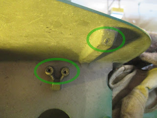
Well, considering I shipped them off to the paint shop after a cursory fit check, then installed them, I had to drill the old bolts and tap them - on the car. That's not exactly a nice experience, sitting on cold concrete (getting polaroids) while trying to keep friction-heat from discoloring paint, or being as careful as I can to not scratch paint with spinning grinding stones, drill chucks, or tapping handles. Trust me, it was a pain. Here are some examples :

In the above photo, I've circled two spots. The lower left is where a plastic clip bolts on - and the bolts were frozen (the heads snapped off). I've already drilled and tapped the holes. The 2nd bolt was a side bolt, and I didn't grab a picture of that - I'd already drilled, tapped, and installed the limit bracket. The upper-right one is the bolt how where the front, surrounding bezel bolts to the lid. I saw that, and about spit oil all over the place. I checked the other three just to get an angle at which to drill .... only to find all four of them snapped off. [sigh].

Make sure you do your home work, and stop trying to pass off broken as "working". Your lies only cost people time!
Oh, and if you are having to drill and tap holes in these units, just remember, the units are soft metal, while the bolts are hard. It's easy to go off center, and the drill bit will move to drilling the units instead of the bolds if given the chance.
Friday, October 23, 2015
Headlight Covers Installed
Well, I finally had a little time to break away from other projects and look at one that has been waiting for months, and tackle the installation of the headlight covers. There are four painted parts - the "lid", and the "bezel". The bezel wraps around the headlights themselves, and the "lid" is the plate above them that (when closed) is "flush" to the body lines.
To install them, you first have to get the lids in place. There are two brackets on each end that pivot, with a lock collar to prevent the lids from sliding back and forth. You have to get the lids in the right position (both up and down) before you tighten those brackets to the frame. It's a pain, because those pivot brackets extend beyond the width of the hole that the lids drop into, so it has to be done at an angle, then with pressure to slide them into place. Once that is done, you tighten the brackets while holding the lid as close to position as possible. You can't do it with the lids in the closed position, because it doesn't allow you to reach around, hold, and tighten at the same time.... that means it's a lot of guess work. So.... you install the lids as best you can....
.... only to find the lid doesn't close because it's too far rearward. So.... loosen all six bolts holding that lid in place, reposition, retighten while pulling the lid forward, and let the lid down slowly....
.... only to find it's sitting too low. Loosen them, this time pull forward and upward from those pivot points while tightening. It was still not enough, so I had to measure around the lid to ensure I could get it centered. Then, I removed the whole lid, then drag out the dremel grinder enlarge the holes so I could put it in (I also enlarged the wholes upward because it was still low. Put it back in, tightened it down while pulling it forward and raising the back.
Viola! Then I had to repeat it for the other side.

In the process, I nicked up the paint around the hole.


That means I have to touch it up tomorrow (not quite the same color, but if it's close enough, it's good enough). I'll let that set for a couple of weeks, before I proceed to do more. However, it does look good when I stash the bezel into position.


Woohoo! I still need to finish it off after procuring a set screw for one of the lock collars on the left, and then it's all working on hardware inside to ensure a smooth operation. Then, I can finally finish the electric headlight conversion!
Wednesday, October 14, 2015
Rebuilt: Grinder Assembly
I'm kinda glad this one was a smaller project. It took about 8 hours of labor, stripping things down, cleaning, priming/painting, then re-assembling.

Just a note, I couldn't (for the life of me) figure out the left side stone removal - the nut just wouldn't come off. It took me a bit to realize it was a reverse thread, and "loosening" was actually "tightening". Once reversed, it came right off. Silly me!
 I tried to leave the tool supports original (no refinishing, just a good brushing of the rust off), and re-threaded all of the bolts so they'd slip on easier. I SHOULD have added washers.
 The oil cups on top were plugged, so I cleaned those out, and wiped it all down before painting. It was originally a "red", but I didn't have any of that paint laying around, so I painted it to match the lathe. The motor is a 115v "Bendix 14080" 1/4 HP A.C. motor (not sure of the RPM it puts out) :

Sweet!

Just a note, I couldn't (for the life of me) figure out the left side stone removal - the nut just wouldn't come off. It took me a bit to realize it was a reverse thread, and "loosening" was actually "tightening". Once reversed, it came right off. Silly me!


Sweet!
Wednesday, October 7, 2015
Checking the Lathe Bed Ways
On my #534.0601 Dunlap early 1940's wood lathe, I had to have the bed welded (a crack just under the ways on the tailstock end). The welder (an older gentleman, who has been doing welding for decades) took it and brazed it. To braze it, he ground the edges, put it over a furnace and heated it up red hot, then added material. The problem with brazing is that it has to get red hot - which causes cast iron to warp. On getting it back a few days ago, I knew I needed to check it for flatness to ensure things would be within specs.
However, I don't have surface for checking the plane of the ways to ensure it's not warped - meaning I thought I didn't have the tools to do it. So, I improvised. The next best thing was sitting in a gun case.... I had one of those laser sighting tools that sits in the chamber. I grabbed that, threw it into the drill chuck on the headstock, and slowly adjusted it until I had it spinning without any run out (I hand turned the spindle - I didn't want it too fast).


This gave me a line-of-center from the headstock through the rest of the lathe. I tossed on the tailstock (closer to the headstock) :

I aligned the tailstock with the laser, and then adjusted the extension on the tailstock to make sure it was lined up. It looked great. I slid the tailstock back a little bit, and checked it again. I repeated this process multiple times until the last 4" of the ways - and saw some drift. There was some slight warping from the heating. I should have used a scraper to remove the warp, but I instead used a bastard file. It took a couple of runs at it before it brought it back in line (it was about 0.05" off). I am now the proud owner of a completely operational 534.0601 wood lathe with the metal turning attachment.
However, I don't have surface for checking the plane of the ways to ensure it's not warped - meaning I thought I didn't have the tools to do it. So, I improvised. The next best thing was sitting in a gun case.... I had one of those laser sighting tools that sits in the chamber. I grabbed that, threw it into the drill chuck on the headstock, and slowly adjusted it until I had it spinning without any run out (I hand turned the spindle - I didn't want it too fast).


I aligned the tailstock with the laser, and then adjusted the extension on the tailstock to make sure it was lined up. It looked great. I slid the tailstock back a little bit, and checked it again. I repeated this process multiple times until the last 4" of the ways - and saw some drift. There was some slight warping from the heating. I should have used a scraper to remove the warp, but I instead used a bastard file. It took a couple of runs at it before it brought it back in line (it was about 0.05" off). I am now the proud owner of a completely operational 534.0601 wood lathe with the metal turning attachment.
Friday, October 2, 2015
Memory Leak, Alarm Server, and Valgrind
Note - the output listed here comes after the process was followed, so you won't see the real memory leaks. Sorry I didn't retain them for posterities' sake.
I had a problem. My alarm server was having some major issues, and would stop functioning at random times. There was no core dump to look for crossed signals (no odd null-termination things that I am used to). However, after a little digging, I found that the process was getting sniped - meaning the Linux kernel was killing it - because it was running out of memory. Not cool. I didn't really know how to go about fixing the problem, so I band-aided the thing by putting a cron to reboot the device once-per-week. I ran with it in that configuration while working on other priorities for a couple of months. Also not cool, but it kept the security system online while I went and handled my growing project list.
So, I started researching ways to isolate the memory leaks. One tool stood out as the best one to use (command-line based), and would work with a natively-compiled ELF binary.
Valgrind
Val grind does a lot of things, and memory leak detection is just a small slice. I downloaded the source, and compiled and installed it (using the standard "
I started the application again, let it run for a few days, and broke out of it once again. This time, I had line numbers in the output. Hallelujah!
... I had the wrong variable I was using to allocate a chunk of memory. I made the fix, re-compiled, and had instantly narrowed down the memory error contexts to about three basic memory errors - things where I was using NULL-termination-requiring functions on variables that may not have had the termination and a MySQL error leak. I fixed the NULL-termination errors, recompiled yet again, and had only the MySQL memory leak (appears standard with that version, which is very old). No more memory leaks!
I had a problem. My alarm server was having some major issues, and would stop functioning at random times. There was no core dump to look for crossed signals (no odd null-termination things that I am used to). However, after a little digging, I found that the process was getting sniped - meaning the Linux kernel was killing it - because it was running out of memory. Not cool. I didn't really know how to go about fixing the problem, so I band-aided the thing by putting a cron to reboot the device once-per-week. I ran with it in that configuration while working on other priorities for a couple of months. Also not cool, but it kept the security system online while I went and handled my growing project list.
So, I started researching ways to isolate the memory leaks. One tool stood out as the best one to use (command-line based), and would work with a natively-compiled ELF binary.
Valgrind
Val grind does a lot of things, and memory leak detection is just a small slice. I downloaded the source, and compiled and installed it (using the standard "
./configure && make && make install" stuff). I did many Google searches, and finally came up with the following command to launch the server inside of Valgrind for memory leak detection :G_SLICE=always-malloc G_DEBUG=gc-friendly valgrind -v --tool=memcheck --leak-check=full --num-callers=40 --track-origins=yes --read-var-info=yes ./eventserver/server/eventserver -bf ./eventserver/server/eventserver.conf > valgrind.log 2>&;1
==12262== 891 (108 direct, 783 indirect) bytes in 9 blocks are definitely lost in loss record 86 of 93
==12262==    at 0x482CF8C: malloc (vg_replace_malloc.c:236)
==12262==    by 0xAA59: eventserver_key_set (config.c)
==12262==    by 0xAB55: eventserver_sensor_create (config.c)
==12262==    by 0x4D4DDA9: arduino_handle_request (arduino.c)
==12262==    by 0xC795: eventserver_process_hook_socket_handle_incoming (process.c)
==12262==    by 0xDC0D: eventserver_main_connection_handler (main.c)
==12262==    by 0xE29D: main (main.c)
==12262==
==12262== 65,550 bytes in 5 blocks are possibly lost in loss record 91 of 93
==12262==    at 0x482CF8C: malloc (vg_replace_malloc.c:236)
==12262==    by 0x4DA5A23: my_malloc (in /usr/lib/libmysqlclient.so.16.0.0)
malloc, and memory pointer problems using strchr. Since the files referenced called the functions numerous times, I didn't have much to go on. I went back to Google, and found some additional information. Apparently, using some compilation flags to gcc, you could add gdb debugging information, such as line numbers. I manually added the following to the CFLAGS in all of my make files :-g -O0
I started the application again, let it run for a few days, and broke out of it once again. This time, I had line numbers in the output. Hallelujah!
==12262== 891 (108 direct, 783 indirect) bytes in 9 blocks are definitely lost in loss record 86 of 93
==12262==    at 0x482CF8C: malloc (vg_replace_malloc.c:236)
==12262==    by 0xAA59: eventserver_key_set (config.c:219)
==12262==    by 0xAB55: eventserver_sensor_create (config.c:256)
==12262==    by 0x4D4DDA9: arduino_handle_request (arduino.c:228)
==12262==    by 0xC795: eventserver_process_hook_socket_handle_incoming (process.c:257)
==12262==    by 0xDC0D: eventserver_main_connection_handler (main.c:494)
==12262==    by 0xE29D: main (main.c:669)
==12262==
==12262== 65,550 bytes in 5 blocks are possibly lost in loss record 91 of 93
==12262==    at 0x482CF8C: malloc (vg_replace_malloc.c:236)
==12262==    by 0x4DA5A23: my_malloc (in /usr/lib/libmysqlclient.so.16.0.0)
... I had the wrong variable I was using to allocate a chunk of memory. I made the fix, re-compiled, and had instantly narrowed down the memory error contexts to about three basic memory errors - things where I was using NULL-termination-requiring functions on variables that may not have had the termination and a MySQL error leak. I fixed the NULL-termination errors, recompiled yet again, and had only the MySQL memory leak (appears standard with that version, which is very old). No more memory leaks!
Sunday, September 13, 2015
Security Cameras are Pointless
Sometimes, having a security camera is pointless. Here is one of those times :
If you can't prevent the hurt from your eyes, how do they help? Thanks for the laughs, Jeff and Mike!
Monday, August 24, 2015
Bringing Compassion (Ashley Madison)
In June of 2015, a breach of security happened with a company called "Ashley Madison" - a purveyor of cheating spouses, secrets, and probably a lot of illicit behavior. Under request of someone I know, I obtained the data from that event, trying to run a little bit of profiling. The data (compressed) occupied over 10Gb. That is a lot of data. It expanded to about 20Gb. That is a ton of data. When I imported into a temporary database, it expanded to around 45Gb of data. Yes, 45Gb of damning, dark data.
Curiosity got the better of me and I wanted to do some statistics on it. So, I tried running a few numbers. In the process of running a few numbers, I accidentally forgot to pipe the data through the counting mechanism on a single command (I did not make that same mistake again), and it started dumping names to the screen. As I frantically smacked "CTRL-C" over and over and over in an attempt to cancel that, I was unfortunate enough to witness a few names scroll past. These were people that I knew. These were people that I had full respect for one week ago.
That happened two days ago.
I cannot get that out of my head. As much as I'd like to say that I am not judging, deep down I can just feel the results of their heavy falls from the pedestals on which I had placed them. The reverberations of simply knowing someone elses sin can lead to two reactions:
Now, what do you do when you know this? How do you react? The age old question, what would Jesus do? It brought to my mind the incident of the Savior, when the woman that was caught in adultery was brought to him. There were two teachings that came about when this occurred:
So, how should we be reacting? Do you want to be the first to cast stones? Or even the last? I grew up at dear old Davis High School. I hated high school. I was an outcast. I know what an outcast feels like. I have been there. I have experienced it.
Here are some numbers. In Kaysville, Utah (population of 28,000), there were 932 credit card transactions. Of those, there were 140 people caught up in that in the city. In Centerville, Utah (population 16,600), there were over 900 people caught in the data leak. In Bountiful, Utah (population 43,000), there were over 1200 people caught in that. That is well over 2 thousand people that many call neighbors, friends, or family that fell victim to the desires that should be kept between husband and wife. That is the fall of Helaman's 2000 stripling warriors.
As these people begin to pick up the pieces of their lives that have just crumbled to the ground in a big pile of crap, please take time to do a few things :
Curiosity got the better of me and I wanted to do some statistics on it. So, I tried running a few numbers. In the process of running a few numbers, I accidentally forgot to pipe the data through the counting mechanism on a single command (I did not make that same mistake again), and it started dumping names to the screen. As I frantically smacked "CTRL-C" over and over and over in an attempt to cancel that, I was unfortunate enough to witness a few names scroll past. These were people that I knew. These were people that I had full respect for one week ago.
That happened two days ago.
I cannot get that out of my head. As much as I'd like to say that I am not judging, deep down I can just feel the results of their heavy falls from the pedestals on which I had placed them. The reverberations of simply knowing someone elses sin can lead to two reactions:
- Throw stones at them (stones could be ridicule, insult, or even turning away from them)
- Give them a little room and allow them to try and pick up the pieces of their lives
Now, what do you do when you know this? How do you react? The age old question, what would Jesus do? It brought to my mind the incident of the Savior, when the woman that was caught in adultery was brought to him. There were two teachings that came about when this occurred:
- No one is without sin, so be careful about casting the first stone
- If you are the one caught in it, stop doing it.
So, how should we be reacting? Do you want to be the first to cast stones? Or even the last? I grew up at dear old Davis High School. I hated high school. I was an outcast. I know what an outcast feels like. I have been there. I have experienced it.
Here are some numbers. In Kaysville, Utah (population of 28,000), there were 932 credit card transactions. Of those, there were 140 people caught up in that in the city. In Centerville, Utah (population 16,600), there were over 900 people caught in the data leak. In Bountiful, Utah (population 43,000), there were over 1200 people caught in that. That is well over 2 thousand people that many call neighbors, friends, or family that fell victim to the desires that should be kept between husband and wife. That is the fall of Helaman's 2000 stripling warriors.
As these people begin to pick up the pieces of their lives that have just crumbled to the ground in a big pile of crap, please take time to do a few things :
- Give them a chance to change. The Savior did that very thing so many times.
- Remember that they are now fighting a battle that we have never even imagined. It is resulting in life-ending suicides, divorces (and future divorces), and shattering of everything they have ever known.
- Please bring compassion to the table. They are going to need as much compassion as they can get.
I am personally grateful that I know the Savior's atonement applies to everyone, including those caught in the Ashley Madison leak. We need to remember that at the judgement of God, our own "Ashley Madison" data leaks will occur. Even now, every bad thing we have done is already known. We cannot hide that fact. It all comes out in the end.
So be kind. They get to experience a little of that judgement earlier than we will. And we will experience it.
Monday, August 17, 2015
3D Scanning - Proof of Concept
Just as a test, I grabbed the Skanect software, an adapter for the Kinect 360, and the sensor from our Xbox. I wanted to see if I could scan something in. The best thing I could think of quickly was the broken down tiller. It didn't turn out too bad!
https://drive.google.com/open?id=0B-DqTExptE5aRjBXTnZOUG1GaUE.
I also exported it and imported into Blender :

A try at embedding it in the page (might take a while to load, since it's 57.3M) :
Saturday, August 15, 2015
Lathe Compound Slide Refinished
I received the compound slide for the lathe yesterday, and promptly (of course, after mowing the lawn and spraying herbicide all over the lawn to try and kill the weeds) set to work cleaning it up and refinishing it.


The first thing to do was to take it apart. Yeah, you read that right.... I want to take it apart, and there are two reasons for that. First, I want to have every part cleaned - no old grease, no rust, no dirt, no old metal flakes in there. Second, I repainted the lathe, and it would be fairly nice if the tooling matched. So, off I go.

Surprisingly, it only took a few minutes to have it in pieces. I already knew the carriage (the bottom casting) for this lathe matched the right part number (L2-51). I didn't know if the rest of it matched up.

The swivel slide (the second cast iron piece) did match up as well (L2-52). It is separated from the carriage (L2-51) by way of the compound rest swivel (part 9-301):

I could not validate that casting as it was aluminum, and had no part number stamping. Riding on top of the assembly is the tool post slide, part number L2-53 :


While apart, I wanted to know if the tool post slide could be replaced with something that would allow me to use the lathe as a simple mill. It's a nice angled mechanism that keeps things in a solid state, so there is no reason why we can't :


Once I had it apart, I threw some acetone at the parts to clean the old paint off. This took the longest chunk of time. I had already picked up some self-etching primer from Sherman-Williams, so I masked off the surfaces that weren't painted with machine gray, and sprayed primer all over.


I used two coats of primer, and then sprayed three coats of Sherman-Williams blue. I had used the cap that was a close match to the original blue (the cap was slightly lighter in color, but you know, that "cap indicates color" thing means it should be close enough). Unfortunately, the final blue was more of a sky blue. Yeah, the cap color was half way between the original blue and the color of the sky. Still, it doesn't look too bad :


While at it, I dismantled the tool rest, the tailstock, and the headstock for the lathe, and cleaned up and painted them. The only thing left to refinish is the lathe bed. I can't test-fit the tools to the lathe bed, either, because I just don't have it right now - I had sent it off to a good ol' welder to braze a crack. But, as soon as it comes back, it will be time to take the labels off the bed, strip the paint off, and refinish that, too. Then I can put it back on, and find a milling attachment for the compound slide. Woohoo!
Saturday, August 8, 2015
Shop Footprint - Lathe Table Hack
I don't have a lot of room for a "shop". Actually, I do have room. It's about 5'x10'. That's not a lot of room for anything but storing tools, not actually using them. As a result, I'm all about trying to reduce my "shop" foot print.
One thing I've acquired is an old Craftsman wood lathe (becoming a wood/metal lathe). It came with a table under it that was fairly solidly built (half-square steel channel, welded together) - about 2'x4'. There is a problem with the table ... it's heavy. So much so that it is a bear to move to where I can use the lathe, and then put it away.
So, I opted for the next-best thing. I welded a steel square tube to the feet, drilled holes, and painted it. It allows me to throw caster wheels on when I need to move the thing around, and take them off when turning. Sometimes, I amaze myself (you should be thinking, "if that's all it takes, there are probably issues there).


While I was at it, I welded some angle iron to the frame, and riveted a chunk of peg-board up. That allows me to keep my tools with the lathe, without them being in the way. I also riveted a hinge (simply a "custom angle anchor") and another piece of peg board up, and had a sand-paper storage on the tool "rack".

On the other side of the peg board, I riveted a plastic storage container down to hold spare chucks, spindles, etc.
I also grabbed some 1/16" wire "rope" (cable), and connected a hammer, a wooden "mallet surface" (something I can hit with the hammer and not damage tooling), and a printer rod...
... wait, what?

Yeah, a printer rod. I took a printer rod, cut it down to size, and, since it had a hole in one side, I cabled it up to the lathe. It is a perfect size to slip inside the headstock spindle and is used to drive out the Morse Taper #1 (MT1) bits. Since it's cabled to the table, it's always available. Now my table is complete, mobile. The next task is to add some adapters to add a lead screw, making this a complete metal lathe with a compound slide. I already sold my AK47 - the funds are helping purchase a 3D printer! Can't wait!

Subscribe to:
Posts (Atom)