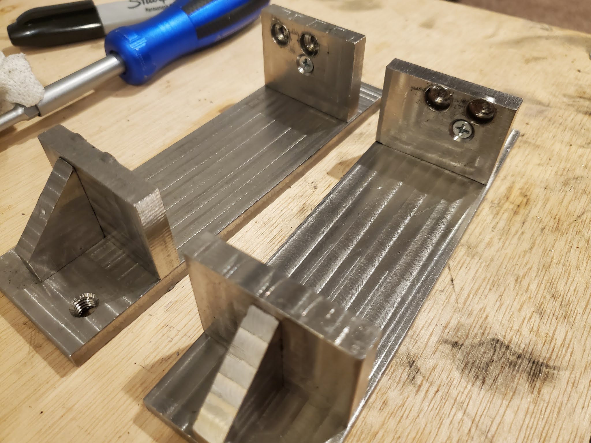
Well, a buddy of mine sent me a concentricity tool. He loves reloading ammunition, and he had an extra. Knowing that I dabble with machining, he sent the extra to me to see what I think.
Frankly, it's a terrible design.
The tool itself is in the upper, right-hand corner of the picture above. Dovetails on the frame are great for maintaining parallelism, but the problem here is that the cartridge is held by the two ends. One of those ends is the bullet. Now, think of trying to see how concentric the bullet is when one of the reference points is the bullet itself. You will NEVER get above 50% in accuracy, meaning if the bullet is out 0.020" that it will never read above 0.010". That means this tool will be lying to you, no matter what. Granted, I went out to do a search, and some manufacturers do it better, but I'm not going to go spend a hundred bucks or so as a gift to my buddy. Instead, I'll spend twice that and make one. Isn't this how engineers and machinists work? We know we can always do it better.
That started me off on this whole "concentricity tool" design, as done from the perspective of a machinist. Knowing you can't use the bullet as the reference point, and knowing you could use the shell casing itself, I threw together some plans for the hobby machinists, and then started to make one or two (it's easier to make a second - not sure who will end up with the second one as people don't associate me with firearms).
Here's the resulting BOM (Bill of Materials) :
- Stainless Steel flat bar stock (I used 2" x 3/8" x 36" and had enough for two tools)
- Bearings (I'm using 624zz bearings that have a 10mm outside diameter, 3mm inside diameter, and 4mm cross depth)
- 5/8" stainless steel round bar stock
- Screws (plans called for #10-32, I'm using #8-32)
The tools needed :
- Milling machine (optional, really, depending on how crude you are willing to have the tool - it's used to flatten and square up the flat bar stock, which isn't critical to the operation)
- Lathe (if you want to test the true concentricity, this is absolutely a must so that the bearing areas of the rollers are concentric with the outside of the rollers)
- Drill press (you could use a mill, if you get the right speeds)
- #27 drill bit (tapping) and #18 drill bit (close fit) for the #8-32 screws
- Countersink bit to let the screws be sub-surface
- Transfer screws to match the screws you are using to the bar stock
- Taps to match the screws in your bill of materials
- Center punch (I used an automatic)
So, here's how I got from point "a" to point "b".
First, I ordered some stainless steel bar stock. I'm using 3/8" hot-rolled, and while the plans called for 1.5"-wide, I ordered 2"-wide stock. Oh, well, larger is going to be a little more solid, but still usable. Once in hand, I sliced off 8 pieces (I'm doubling the parts, right?). The first two were 7" long, the next four 1.5" long (for the sides), and two 1" long sections for the "gussets". These two gusset parts will be cut at an angle to yield 4 parts down the road.
With the cut list done (bandsaw cuts are rough), I began to mill things square. I milled the gusset blocks, and the sides square. Two of the sides were milled 1/8" shorter, as one end of the devices will allow for clearance if a larger cartridge is to be used (4" is large enough, but you never know what some expert will try).
Note, we still had those "two" square gussets - and we need four. They were marked on the height with the small side, and then I could scribe a line for them at an angle. These were run out to the bandsaw for a quick cut.
Bandsaws leave a terrible finish. The angle was a custom angle to get two gussets out of each one, so I couldn't readily calculate the exact angle without having a gusset too tall. So, we clocked the newly-cut gussets into the vise using a bit of a trick. I took 1/8" stock as "risers" and a longer flat piece to stretch over the two risers, and set them on the vise jaws. Then, I slid the gusset angles that had just been cut up against the longer flat piece.
This let me cheat and set the angle for these things so that it was close to the top of the vise, but gave enough clearance to get it milled flat. Again, the angle wasn't critical, but it needed to be short enough on the tall side to not exceed the short side.
While I was finishing the milling (you can see in the last picture that the base is still "raw", I milled the base's top surface, and then "about" 1/2" on the bottom surface so I could have a parallel surface to put rubber feet on and protect furniture if the users so choose to use this in the kitchen.
With the mill work complete, it was time to drill. I was only going to drill all of the holes that were threaded, not any of the matching through-holes. This was so that each piece could be matched for a good fit.
All I had to use was a cheap titanium nitride drill bit (a cheap Harbor Freight set). I'm not going to rant or rag on the quality of these drill bits - they helped me get my foot in the door. Also, I later realized that it wasn't my drill bit that was the problem, it was how fast I was spinning the drill bit. Still, I did a little cussing about cheap Harbor Freight specials at the time before I really understood that the problem wasn't the tool, the problem was the tool who was operating the tool. Anyway, I had it marked up :
I must say, though, that you do not want to use Titanium Nitride drill bits on stainless steel. Sure, it might work, but just do yourself a favor and get some cobalt (or carbide) drill bits. If not, and with the spindle speed way to fast on the mill, you get things like this :
And, just in case you could 't see that close enough, here is the same picture cropped a little so you can see what the stainless steel did to the drill bit :
How about that inverse curve on the point? Yikes. I've already got the 10mm end mills for boring out the roller bearing bores (should match up), and I have the 8-32 transfer screws (I opted for a change since I milled enough material off). Once I got the replacement drill #27 drill bit, I quickly dulled one on the mill, and decided to just go to the drill press. That worked much better.
I tapped the holes. On one, I stupidly broke off the tap. It's one of the frame sides, so I could easily move the hole for the side closer to the edge and drill a new hole. Also, when drilling one of the gussets, I went just a little too deep, and that gusset has a bulge on it now (I'll just file that off when I'm done and expose the hole). However, those blemishes won't alter the effectiveness of this. Those are simply cosmetic, and one will be hidden because it will be sandwiched between the side and the frame bed. You can see all of the blemishes in the following picture. The two gussets had holes that were slightly off-center on the gussets. All of these blemishes are annoying to me, but most will be hidden.

At this point, mark all of your parts. With what we are doing next for a custom fitment, if you get things mixed up after this, it may not fit together well.
Once all of the drilling and tapping was done for the threaded holes, it was time to start marking the mating holes for the screws. This is where those transfer screws come in. I put the transfer screw into the vertical surface of the gusset (it's the only horizontally oriented screw). I could then mark the parts up with marking fluid (I'm cheap - Sharpie is my go-to, not Dykem layout fluid). With the two parts sitting flat on the frame, I could then use the gusset to mark the vertical point on the side. Then, a caliper to center the gusset screw gave me the point I needed to punch to drill the close-fit hole. I did one centered (the one with the frame and gusset close to the end), and the other end offset a bit to allow for clearance from the dial test indicator stand (about 0.625" from one side).

I got the sides drilled out using a #18 drill bit (close fit for an #8-32). That allowed me to screw the sides and the gussets together. Once that was done, I could then put the transfer screws in the bottom of the side-gusset assembly, put my expensive, high-contrast marking fluid down on the base, and get it lined up. Then a quick whack with a hammer gives drill points. Note, I'm going to suggest six hands here. Seriously, if you have four 1-2-3 blocks, use them. I used a tool makers' vise on the end to keep the gusset flush, a 1-2-3 block braced on the side, and another 1-2-3 block against that to keep the side perpendicular to the base.


I used a center punch to get those marks a little bigger, and then drilled them out. I did one end at a time, starting with the flush side. With one side complete, I dropped my 1-2-3 blocks in place (and kept a flat on the side to keep the side-gusset perpendicular to the frame base). I'm working with a 4"-between-sides distance, so I used the 1" side and the 3" side of two blocks against the face and set the next side in position. Another whack, and repeated the drilling.
Wash, rinse, and repeat for the other tool's frame, and I could screw them together for the first time. They'll be taken apart again for the boring operation for the rollers' bearing cavities. This will let me keep things in place, though, so I don't have to mix up parts.
That gave me two nearly-complete frame assemblies. I marked 0.500" from the the side and the end on the base to locate the hole for the dial indicator stand itself. The dial indicator stands I bought are M8x1.25 metric threads [7.5mm diameter with a thread every 1.25mm]. I grabbed a 9/32" drill bit (best 50% tap fit for stainless steel). I hand-tapped using a titanium nitride tap from Harbor Freight. It got the job done, but there was certainly some pucker power to get it to tap all the way. Once that was done, you can see how this is going to be set up.

To complete the frame assemblies, I need to bore out the bearing cavities, and also drill and tap the frame base to take the dial indicator arm. I used 1-2-3 blocks to mark a line 1" from the outside of the frame base on the sides. This will give a valid measurement, and although it's not critical to the operation (even if the rollers were not parallel to each other, if they roll and are concentric, you'd get valid measurements), I'm doing it because my OCD gets in the way. Make sure that, when you mark them, you are marking them "backwards". When you have the faces out toward you, if you mark them exactly the same and rotate them inward to each other, it won't line up (unless you centered it on that line scribed using the 1-2-3 blocks. So, from that center line, I measured to the outside 0.500". On the short side, I measured 0.500" to the right, and on the other side I measured 0.500" to the left of the scribed line. I measured up 0.1875" from the base and marked the other lines needed for the centers. Then I center punched one hole on each side. Using that as the starting point, I measured 0.620" from that center punch mark toward the other side, and scribed the cross har on the 1.1875"-from-the-bottom line I'd done earlier on each side, and then center punched those.


Now, on each face, I have two center punches that are properly spaced apart for the rollers. Thinking this was going to be a walk in the park on the milling machine (remember, it's a Harbor Freight machine, not big at all), I quickly burnt up my 10mm end mill. No, that's not an exaggeration - the cutting edges are all charred and the outside supposed-to-be-square corners are lifted. Here's me using a center on the hole to line it up on the mill before I went through all of that.
I wasn't going to have the prettiest time doing this. [sigh]. To the drill press!
I know this isn't "accurate". I know the holes aren't even "round" (inside joke - ask a machinist, and he'll tell you that a drill press is just for putting holes in things and that if you need them to be round, use a different machine). But, it's the only thing I have that is able to do it. I started with a 1/4" bit, went to 5/16", and stopped at 25/64". That left a bore about 9.95mm, or about 0.3910". I should have it around 0.3937", that's about 0.003" undersized. Drill bits always drill slightly oversized. I expected the drill bit to produce a larger hole that the drill bit, so in theory it should fit. Anyway, I drilled about 5mm, or 0.196" deep. That is right about the depth of the bearing on the outside edge of the drill bit (remember the cone on the end - we are using that as a bearing clearance end, which I'd originally called for a 1/4" or 7/32" hole that was about 0.010" deeper than the bearing). The drilling left a burr on it.


I filed off the burr, and set the bearings in place only to realize that the drill bit is slightly undersized. The 25/64" drill bit produced a hole that was 0.386" in diameter - 0.007" undersized. This means that the drill bit was quite a bit smaller than it was supposed to be. Hoping that the next drill bit up would be similar (or I might have to resort to brass shim stock to keep bearings in place), I grabbed the "X" drill bit (0.004" larger than the hole I needed, in theory), and enlarged those holes. I ended up about 0.392", so a 0.001701" undersize should work.
I used c-clamps to press the bearings in place, and to keep them on the same plane, I used the base of the second tool as the other end of the clamp. Frankly, you can use anything flat. I was too lazy to go find something, and I didn't want to use the hydraulic press. The bearings still turn, so that 0.001701" was perfectly sufficient to use, and keep the bearings in place.
The frames are complete.
It took me a few weeks to get my lathe running. I'd taken apart the Junior to make room for the final resting place of the Heavy 10, which meant that I didn't have an operational lathe for a while. It also meant that I had to get a chuck of some sort in order to hold my stock - so I had to cut at least one back plate.
To maintain concentricity, the rollers can't just have the bearing areas turned - they'll need the whole thing. This is because if you don't get the bearing area fully concentric with the bar, it will be off. Here's an example.
If you have a bar that you manage to get within 0.0005" (which most machinists will accept as "close enough" when turning on the lathe), you have the potential to have that same 0.0005" off on the other end, too. That's 0.001" out over the full 4". That number is a +/- number, because a cartridge could be placed on opposite ends, which means that it gets doubled (it's a range). If the cartridge was actually off axis 0.006", when you measure it, it could read low or high the "close enough" amount you were willing to deal with. Two cartridges with the exact same concentricity could read as low as 0.005" or as high as 0.007". While a range of 0.002" for concentricity may be acceptable for most people, I'd prefer to keep it as close to perfection as possible.
Are you going to chase perfection? Or just cheat to perfection?
Yeah, that's what I thought. Here's how to cheat.
Chuck up a chunk of round bar in your lathe that is slightly larger than your intended target. I chose 0.610" as my target for the roller so that I can start with 0.625" (5/8") stock. Shove that round bar with enough length in your chuck, and then turn down the entire outside diameter to your roller target (this diameter should be slightly less than the distance between the rollers for clearance). The part's outside diameter is now true to it's axis.
When with the outside turning, and without taking the bar out, turn the tailstock side bearing boss down to size. I'd suggest adding a small 7/32" boss between the main roller body and the bearing body to clear the bearing surface. 0.005" for that will be fine. (That register surface will prevent interference with the roller and the outside bearing surface.) Then you can turn the other end of the bearing surface and boss at the headstock, and then part it off.
This is over 4" long that I'll be dealing with... so I need to use a steady or a follower rest. A steady rest works well for work that you are not cutting the entire length. For example, if you are cutting a screw that is 3' long, a steady is not what you want. A follower rest moves with the carriage, and gives you support close to the cutting tool. With me wanting to turn the full length, either I have to use a steady rest at the tailstock end (or do a live center for support on the tailstock) and have extra waste stock when I'm done, or I have to use a follower rest. The rule for if you need support is this... if the stick out is 4x the diameter, you need support.
With this being classified as long-and-slender (0.625"x4"), I need support. That meant setting up my follower rest for the first time in my life.
After running through all of that, the follower wasn't quite aligned. I wanted it closer to the cutting tool, and things were just... off. When I went back to the chuck end, it bent the raw stock. So, I had to go to plan B. I used a 5/8" 5C collet. Surprisingly, the stock registered as 0.0015" out of round - way better than what I got using the chuck.
With the rollers done, I loosened the screws on one end (the gusset/side assembly) far enough to slip the rollers into the bearing surfaces, then tightened it all back up. Here's a novel idea.... use the tool with the dial indicator to check your work. Or don't if you want to think you did a perfect job. Unfortunately, I DID check my work, and promptly cussed a little bit.
The chuck roller came out about 0.006" out of round, and the collet roller came in at 0.003" out of round.
With the assembly complete (but me cussing a little bit), I grabbed three cartridges - one factory load 308 (atomic something or other), one 308 reload that my buddy had put together, and an old .50 caliber from World War II that had been fired (primer pin divot).
The .50 caliber was just used to check capacity. A test after a repair gave me 0.030" range (0.015" off center in one direction). This will never be fired (a bullet put back into a used cartridge, known as a "dummy round") so I don't really care about this one, but it sure did look awesome.
The factory load cartridge was checked on the Hornady. I did it in two places just to prove my point. First, the bullet end pretended to be really well done and registered 0.002" off center. Using the neck (at the mid point), it registered around 0.00725" off center.
I moved it over to the roller, and saw things registered at 0.015" - and no, that is NOT a misplaced zero. The factory cartridge registering at 0.007" off center on the Hornady clocked in at 0.015" - and confirmed that if you check the cartridge at the mid point, you're only getting half of the story.
Using my bud's reloads on the Hornady, it registered 0.002" off center. If my brain hadn't wrapped itself all over the math on it, I'd have sworn that would have been a perfect cartridge.
But over on the roller, I got a slightly different story.
The numbers came in at 0.008" off center. Wait ... 0.002" to 0.008" ? That is a pretty big difference if you are trying to push down range in competition, if you ask me (but you didn't, and I still told you). However, my brain is telling me that I have 0.006" off center on the rollers, which is a 0.0035" off center in one direction, as the baseline. That could mean that the factory load on my little roller added 0.0035".
So, all of that work, and the range of potential results killed me. I rebuilt a new roller to replace the one I must have mangled on the chuck, and re-measured a few things, giving me the following datum (note the Hornady doesn't have the accuracy in the dial indicator, so the numbers will have a little less granularity) :
| Tool | Factory Measured | Factory Potential | Reload Measured | Reload Potential | .50 |
|---|
| Hornady | 0.007" | 0.007" | 0.002" | 0.002" | no capacity |
|---|
| Off Centered | 0.0150" | 0.0150" | 0.0075" | 0.0040"-0.0110" | unmeasured |
|---|
| SilverHawk Special | 0.0110" | 0.0110" | 0.0035" | 0.0035" | 0.0300" |
|---|
| Difference | 0.004" | 0.004" | 0.0015" | 0.0015" |
|
|---|
With the difference between the Hornady and the new tool being no more than 0.004", the Hornady will still do the job. If you just multiply by about 2, it will get you in the ball park, and most reloads are simply looking for a range, anyway.
That was a long way to get from the "I can do that better" to the result that consisted of "sure, it's better, but I probably should have just been lazy."