Friday, December 26, 2014

Countdown Clock - Stratum 1 Not Required

Well, someone has tasked me with building a "Christmas Countdown" clock.  A couple of blocks away from our house are a few houses that have been referred to as "Yards in which Walmart threw up" - meaning they had so many "cheap" decorations that they essentially didn't have a yard.  One of these homes has a countdown clock in the front window.  We'll call this "The House" in this post.

A neighbor of mine loves Christmas (he is a good friend of mine).... to the extent that the family has to drive past The House every day just so he can see the clock.  He doesn't work a soldering iron at all, but he has requested that I build him a custom countdown clock.

First, I needed a good way to count down to a target date/time.  I didn't want something attached to a network (e.g. using "NTP), and I didn't want some fancy clock that had Stratum 0/1/2 (which, incidentally, are all NTP - I know this, but I'm simply using that as a reference point so that you can understand that I don't need accuracy over a long period).

There are a number of ways to create a clock.  They are broken into two categories - analog and digital.  An analog clock is (usually) simply a motor and gearing to move the hands on the dial.  The digital requires a signal input - often referred to as a "clock" (go figure).

Because he wants a days/hours/minutes until Christmas clock, it should probably be digital.  I can go the highly-accurate way and procure a crystal oscillator and design a circuit around that, or I can simply use an inaccurate oscillator - the infamous 555 timer. For the purpose of this, expecting it will be used once a year for only a couple of months, I'm settling on the 555 timer.

With that settled, I needed a circuit.  I really needed something fairly accurate to the 1/1000th of a second.  Here's a circuit that should give you pretty good results :


The thing I see wrong with the circuit above is it is about a 66% duty cycle, meaning that the output will be "high" 2/3rds of the time.  I'd rather have it closer to a 50% high, 50% low duty cycle.  But it also has to have that accuracy.  Let's tackle the accuracy first.

There are 86400 seconds in a day.  If we are slightly off by 0.004 seconds, over one day, we lose almost 346 seconds.  That's 5 minutes we lose (or gain) every day.  Let's say we are only using the clock from Thanksgiving until Christmas.  We'll round it to 30 days just for the sake of simplicity.  That turns out to be 10368.0 seconds over the 30 days, or 172 minutes, or nearly 3 hours over the course of 30 days!  Probably unacceptable.  Even if we are at 0.001 seconds off every second, it still comes out to about 43 minutes over the 30 day period.

That means I have to get this pretty close (unless I have to procure a crystal).  With that out of the day, here's the formula for figuring out the resister/capacitor combination :

f =1.44
(R1 + R2) x C


So, now we have to do some math.  We want the frequency (f) to be 1 Hertz, or 1 cycle per second.  To get this, we have to have the capacitor times the sum of both resistors equal to 1.44 .  I wanted at least the R1 to be a standard value, and I found that I can put R1 to a 1k Ohm resistor - that's common enough.  Also, a common capacitor is 47 uf, or micro farads.    I can plug that in where the "C" is in the formula.  It means I now have a formula that looks like :

r2 =1.44 - (r1 x C)
C

So, what is the result of the math?  Unfortunately, it came out to just under a 1k Ohm resistor (969.361 Ohms).  But looking at some 555 timer calculator sites, it says I need a 14.855k Ohm resistor (or a combination that adds up since they don't make a 14.855k Ohm resistor).  I must have done my math wrong.  Back to the drawing board!

Thursday, November 27, 2014

The Roof WAS on Fire

Well, we replaced our roof.  Luckily, I changed jobs, and the vacation time I had accrued essentially covered the materials.  My family is awesome!  They came up (or down, depending on which family it was) to help out.  They did amazing work!  The old roof looked pretty old :


With all of that cracking, one would think it's really old.  Unfortunately, when we tore the shingles off, we found some surprising stuff :


Yes, underneath it, we found green tar paper nails, and ice and water shield!  That means the roof was less than 15 years old.  A single layer of shingles, 15 years old, curling like that... it means that there was too much heat in the attic.  We cut a few more holes for vents, removed the vent that was in place for the wood burning stove in the basement, and dropped some new OSB over the top.  Then we put a new roof on.  Hooray!

Saturday, November 15, 2014

Headlight Wiring - Plan, Participate, Prevail

So, after perusing the Internet trying to figure out how to implement electrical headlights, I finally knuckled under.  I had seen a few people use full actuators, and others who used some old Mazda Miata or Ford Probe headlight motors.  With the costs of actuators running to $200 a piece for a 4" movement (and needing one for each side), I realized I was too cheap.  I had to do the Probe conversion.

I ran to the closest junk yard, and found a mid-90's Ford Probe.  I pulled the motors and arms attached to the motors and paid about $30.  I ran home and tested them against the battery.  Woohoo! They both worked!


Next, I had to wire them up.  I didn't want to cut into the old harness at all in case I wanted to back this out some day.  So, I grabbed three spade connectors - these would plug into the current 3-prong headlight connector (the one for brights AND regular beam).  I also bought a new 3-prong connector. These would be soldered together with three wires coming off as "taps".  These three wires (one is battery negative, the other two are battery positive when the high beams are on, or the low beams) feed (via two 1 amp diodes to prevent both lights from coming on) into a 12 relay (SPDT, or Single Pole Double Throw, where when on, one is connected, but when off, another terminal is connected).  This is wired to a fuse and to a battery connection.  When the high beams or the low beams are on, it triggers the relay to power one line, and when neither are on, the relay switches back to the other.  These two feed the motor trigger signals.  A second "power" is also run to the motors, and a negative battery connection.  I tested this (test often is vital to make sure it works) via a breadboard first, with LED's to make sure I had things connected right (e.g. when one light was on, the signal light was on, and when the other light was on, the same signal light was on, but one light did not cause the third light to come on).

Once I knew I had the circuit right, I had to implement it. I grabbed a solder "bread board", and soldered everything into place.

Then, I tested it against the real lights and motors.  Success!  I threw on electrical tape to protect things, and applied epoxy to the bread board to seal it in.  When the epoxy had set, I applied more electrical duct tape to ensure it wouldn't cause other problems.


Once it was all wrapped up, I installed it, and tested it once more just to make sure it was good.  Congratulations!  Now I just need the headlight units back from the painter, and I can finish the front end of the car!  Here's my shopping list.


  • 2x Ford Probe headlight motor
  • Brackets (had to make these out of porch 4" post end caps from Home Depot)
  • 3x Spade Connectors
  • 1 3-Prong Headlight Connector
  • 2x 1 Amp Diodes
  • 1 solder board from Radio Shack
  • Wire (red and black)
  • Epoxy


If anyone wants to convert, it's not too difficult!

Sunday, October 5, 2014

Corvette Rallys Sold - Paint Picked Up

Well, I got tired of having the Corvette Rally's sitting in the garage taking up valuable floor space.  I put in an add online, and sold the rallys, tires, stainless trim rings and center caps.
 
The rallys were online for the last three weeks.  I think they found a good home.  I know I could have pulled (asked for) more, but I just didn't want to deal with eBay, etc, and thought I'd sell locally.  I was surprised that they sold as quickly as they did (and I'm okay with the price they were sold at).  They'd be used in restoring a 1967 Camaro - perfect!

The beautiful thing is that the actual sale of the rallys came just hours after I learned that the cost from the painter in replicating the paint would be around $400.  Add in the $200 for the cost of a half pint of base color and a half pint of pearl, and we're sitting at $600.  Ouch.  However, this could be valuable information if the painter can do it, and could be worth it to know how many layers of base color, and how many layers of pearl, mixtures, etc.

So, here is the paint information, codes, and labels.  The bill came to $185.71 - The main color was $67.20 for a half-pint, and the pearl was $106.60 for a half pint :


First, the main (base) color  (#908362):

Next, the pearl half pint :


The color chip :

That chip came out too dark, so I had to try one with a flash :
That one looked a little better for the representation of the color.

I delivered the parts and paint to him and he said he'd try to get to it next week.  That would be a huge step toward being finished.

I did find a new color that I thought would be awesome while I was at it for the next project (perhaps a motorbike).  It's Grandeur Blue over Sterling Silver :


Friday, September 12, 2014

CentOS 7 - xscreensaver

I really hate this Gnome interface - badly.  It requires so much clicky-clacky/mouse-moving work that I instantly feel like I'm in Microsoft Windows again.  I prefer a nice, simple Window Manager that is simply that - a window manager.

I have a laptop that I have installed CentOS 7 to - after completely forgetting with a desktop installation - that doesn't have a viable screen saver (unless I choose to go with that abomination called "Gnome").  See, I can't deal with Gnome.  I tried KDE for a week, and half of the time, I couldn't unlock the KDE/plasma screen because it never presented the unlock on it.  I realized that CentOS was not going to make a good desktop/laptop operating system unless I could get to a decent Window Manager and screen saver.

So, I did what every intelligent, awesome, amazing, and brilliant individual would do.  I went down the rabbit hole.  Seriously, I should have taken the blue pill and pretended that Gnome was just awesome - but I don't think I could get beyond comparing it to slicing my wrists and doing pushups in salt water with a hint of lemon juice in it.  I grabbed Xfce (nice - this one came in packages from the Fedora Project epel repository).  However, the EPEL Fedora Project repository still did not have xscreensaver.  That's a serious risk to me.  The last thing I wanted was someone coming by, finding the laptop unlocked, and me returning to find Justin Beiber as my wall paper.

So, I knew I had to compile xscreensaver from scratch.  I ran out and downloaded it from http://www.jwz.org/xscreensaver/download.html and extracted it.  I found a couple of missing packages (aside from the development packages I'd installed previously), and found those in yum :
    yum --enablerepo=base --enablerepo=updates --enablerepo=extras --enablerepo=epel --enablerepo=rpmforge install xorg-x11-server-devel.x86_64 libXt-devel libXpm-devel motif-devel
    
Then..., I tried to compile it :
    make distclean
    ./configure --with-motif
    make
    
I kept running into undefined functions for pthread_join and pthread_create, and thought I was missing a library - but I wasn't.  Down that rabbit hole, I realized I had to patch it.  I tracked down (from the error message) that it was trying to assemble the bsod screensaver and getting those functions, so I opened up the Makefile and started checking it to see how the -pthread was being passed.  After tracking it down, I created the following patch :
    diff -rupN xscreensaver-5.30-base/hacks/Makefile.in xscreensaver-5.30/hacks/Makefile.in
    --- xscreensaver-5.30-base/hacks/Makefile.in    2014-09-11 11:07:53.000000000 -0600
    +++ xscreensaver-5.30/hacks/Makefile.in 2014-09-12 09:48:05.017172709 -0600
    @@ -671,7 +671,7 @@ truchet:     truchet.o      $(HACK_OBJS) $(COL)
            $(CC_HACK) -o $@ $@.o   $(HACK_OBJS) $(COL) $(HACK_LIBS)
     
     bsod:          bsod.o          $(HACK_OBJS) $(GRAB) $(APPLE2) $(XPM)
    -       $(CC_HACK) -o $@ $@.o   $(HACK_OBJS) $(GRAB) $(APPLE2) $(XPM) $(XPM_LIBS)
    +       $(CC_HACK) -o $@ $@.o   $(HACK_OBJS) $(GRAB) $(APPLE2) $(XPM) $(XPM_LIBS) $(THRL)
     
     apple2:                apple2.o apple2-main.o  $(HACK_OBJS) $(ATV) $(GRAB) $(TEXT)
            $(CC_HACK) -o $@ $@.o   apple2-main.o $(HACK_OBJS) $(ATV) $(GRAB) $(TEXT) $(XPM_LIBS) $(TEXT_LIBS) $(THRL)
    
Simply put - the bsod compile instructions missed having the THRL (pthread library) environment variable passed to it.  That was the ONLY patching I had to do.  It still didn't compile because of the xscreensaver-demo until I symlinked the following Directory :

 cd /usr/include/
 ln -s gdk-pixbuf-2.0 gdk-pixbuf

Compiled just fine!


Wednesday, September 3, 2014

Paint Color Matching

I have good news and I have bad news.  First, with both door panels in, a good days worth of work could finish off the interior of the car.  With that in mind, it's time to start looking for a painter for the headlight units.

I called up some paint supply people, and got a recommendation - Larry at Vision Body & Paint, 11265 S 1300 W, South Jordan, UT (801-755-2084).  We talked for a little bit, and (since the paint was done with a gold pearl) now I have a good plan of action.

The color code I had last time was PPG Shimmering Shamrock, 908632 (UPDATE: I'm dyslexic, the code turned out to actually be 908362) 2-coat system.  Calling the supplier again (KC Auto Paint, 1600 S Redwood Road), and they said over the phone that it wasn't green - it was blue.  So now, I've got to run to the supplier with the part again, see if they can match it, grab a pint of stuff (they can mix the color for me), and run it over to the painter to let him try it out.  I think this one trip will cost me $300, but here we go!

UPDATE - I picked up a half pint of base color and a half pint of pearl, and delivered it to a new paint shop - we'll see how well he can match it.

Monday, September 1, 2014

'77 Door Panel with '78 Sport Mirrors and Remote

Wow.  The second door panel is now installed.  This was a bit different, since it wasn't designed for the bullet mirrors and the "remote" mechanism - I had to install it before the door panel was installed.  Here's what I did.

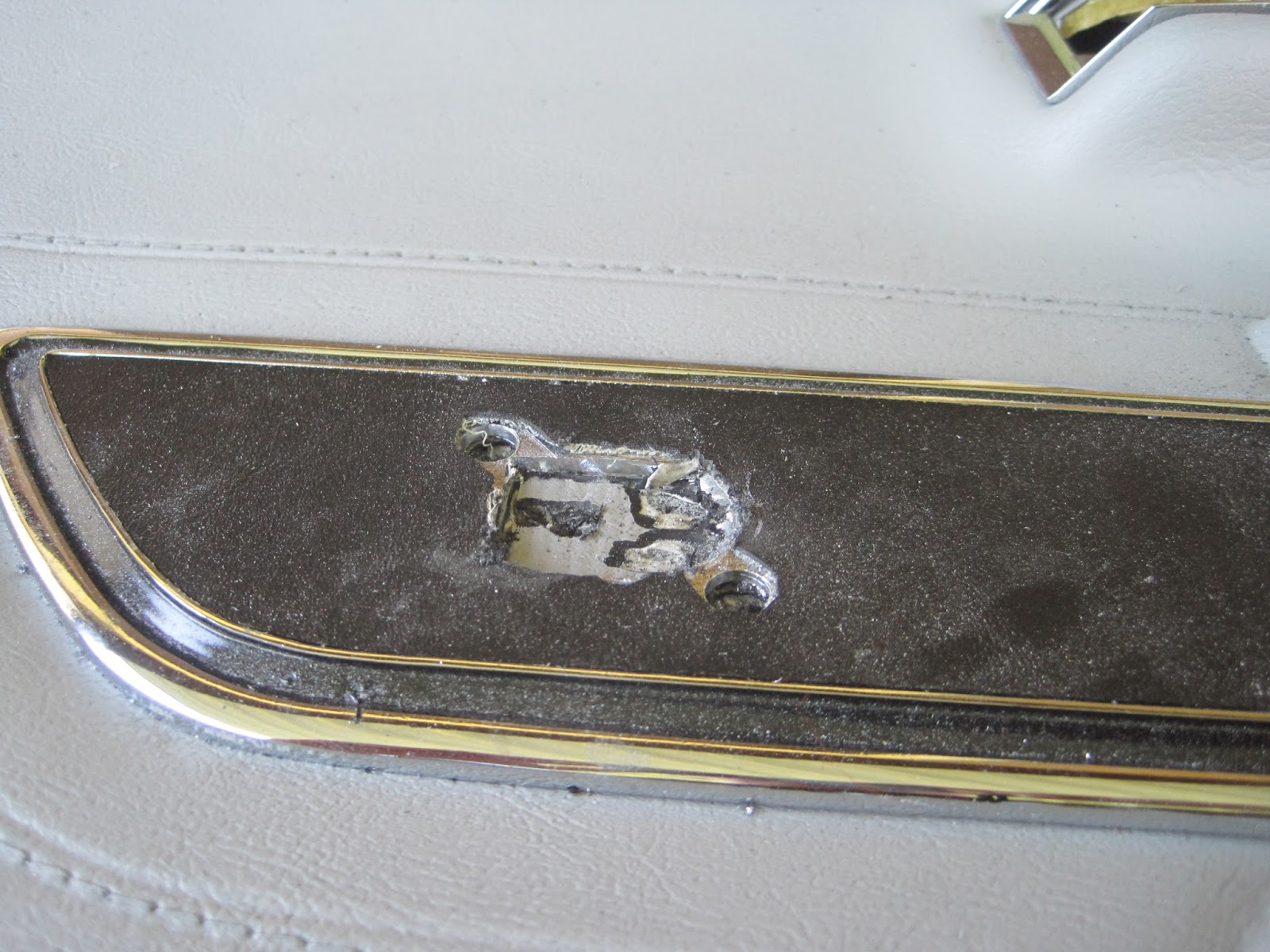
First, I had to mark where the remote connection would be coming through the door panel.  For this, I installed the door panel at the top, and swung it down to put a mark on the black plastic on the back of the door panel.  Then, using that mark, I drilled a vertical hole through the panel.  The problem was that the remote adapter goes through the panel at an angle.  I drilled a second hole through the panel at an angle.

With the approximate location of where things had to be cut, I grabbed my Dremel, and (using the back side of the chrome trim for the remote as a template) started cutting the approximate location:


Once through the trim metal, I found that the "vinyl" for the door underneath.  I used the Dremel again to cut through that, and found black plastic underneath that, too.  Beneath that was the foam, and then the back side of the panel, which was black plastic.  Cutting it out :


I then used the Dremel again to cut around and expand the "square" cut that was a template, making it very much an oval (which is what the chrome trim piece looks like).  Once I was close, I placed the trim piece in position and used an awl through it to mark where the two holes to hold it in place would go.  Then, I drilled them out :


With the trim piece in place, I started to look like it really belonged there :


I had a few minutes to install the door panel :


Looks like it was made that way!