Saturday, February 3, 2024

Storing Pipe Clamps

 Ever since that table project, I've had pipe clamps laying on the floor of the garage, and when it rains, everything is covered in water.  I needed to get them off of the floor.  I used a 2x4 for each end, and I used another one to create the braces to screw that too the wall.  I bored them out using a 1-1/4" Forstner bit, and then finished the cuts for one side (I left the complete hole on the second end).

Bolted them to the wall.

Now, my clamps are off the floor!

Ram 1500 Rack and Pinion Loose

As I've driven my Ram 1500 lately, I've had these weird thoughts that the steering was getting loose.  And then, on Thursday, it started "popping" when I was cranking the steering wheel all the way right and then to the left as I've been parking it.  I panicked, and parked the truck until the most recent snow storm finished.

I slid underneath and inspected all of the steering knuckles and bots to make sure the linkage was in good shape.  Nothing looked off, so I started inspecting everything, and that is when I noticed one of the rack and pinion bolt fasteners (holds it to the frame) had about a 3/8" gap.  I could turn it by finger.  Probably not supposed to be like that.

I grabbed my tools, and secured the bolt.

Now, I don't have the torque specifications for that bolt - and I couldn't find them anywhere (I don't have a service manual for this thing).  So, I slowly incremented my torque wrench and tried the other bolt until I got to the point where the other one would turn.

That is where I put the torque on this loose one.  Steering is again tight, and I feel much better about driving this thing.

Thursday, January 11, 2024

Bernina 900 Foot Pedal Fix Request

I had some family hand me an old Bernina sewing machine (a Nova, looks like a 900 but I cannot confirm this).  It's not working.  The pedal is simply not allowing it to function.  Apparently, they had taken the pedal to a repair shop, and the shop turned them away, because it was only used for a short time, and the parts stopped being made a long time ago.

Granted, they have a few extra sewing machines, but they REALLY like this light weight machine, and were hoping I could get the pedal fixed.  It's called an "air pedal".  It seems to function just like other sewing machine pedals, but it "floats", or at least, it is supposed to.  This one just floated without connection.  So, I took it home, and promptly took the thing apart.

 First thing I noticed is that there is a barbell of sorts used to connect the pedal to the actual hinge hardware, and it is not in position.  Problem?

Perhaps.  The blue circle is around the barbell.  The green circles are two concave holes where the two ends of the barbell are supposed to go (think of a hip joint - one round ball and one socket).

 Here are some more views of the two halves.


Let's put it back together in what we'd call "the Right Way" (trademarked?) and see what happens.

Here we can see the ball joint in it's natural habitat, with the actual pedal ready for installation.

So, was it the actual problem?  Yes. The machine actually started up this time.  It immediately stopped, which sent me home with the whole machine for some electrical tests.

I flipped it over, and a pin fell out (one you might see holding sleeves on a brand new dress shirt that is being opened, not machinists pins or internal pins).  I paused, flipped the machine upright, plugged everything in, and hit the pedal.

Nothing. 

While holding the pedal, I rotated the manual crank wheel, and it started working.  That's it - a pin held the whole thing hostage.  It's back online.

Small Parts Sled

In the process of building the tool chests, I have encountered the need to do some small parts.  Since I do not desire to lose any fingers, and since I didn't want to use my big panel sled used to cut the sides, it was time to tackle yet another sled.  I've seen a Rockler sled listed on Amazon for $90, and it was severely tempting. However, I thought I could save a couple bucks and do it myself, since that sled likely had to be built for my specific table saw, anyway.  So, let's see.

Now, if I filter out the costs of the stuff that wouldn't be included in the Rockler kit, we're looking at the melamine ($20), UHWM ($29), t-track ($36), and a couple of screws that you likely have sitting around for a grand total of $85.

Hold on - I ONLY saved $4?  [sigh].  But, the parts would let me build a second jig if I needed to, say for instance that I was going to build a jig for my router (which IS on the docket).

Anyway, I added t-track folding stops ($28), two t-track hold down clamps (I got mine from Rockler for $8 a piece on sale, but $25 on Amazon for two), an aluminum angle bar for some custom jigging on this thing for $21.  All this, with enough to make a second jig, for $150, and that included stuff the Rockler kit did not for only $60 more.  Off to the build (which you'd have to do with the Rockler kit, too, but most parts are pre-cut).

First, mark up the melamine board for the parts.

The usual cutting of those parts out (yes, I have quite a bit of left over material - I could build a slightly larger sled, or [again] a sled for possibly cutting some custom grooves on the router) went pretty quietly.

With parts cut out, it was time to install the UHMW (again, slicker than HDPE, and the stuff I ordered came pre-drilled).  Note that in my case, my table saw miter slots are NOT 3/4", so I had to use the table saw to trim the width down - and that was a bit harrowing because the blade wanted to grab that material BADLY and throw it at me.  Please take note of your own table saw slot dimensions!

The first bar went on relatively straight forward.  I used a 90-degree square (a carpenters square will work, too - pretty much anything that will get you close) and simply attached it to the bottom.  It didn't have to be on the table saw to get it set into the right position.  I actually set it on the left side when looking at the bottom, about an inch away from the side.  This would become the right side of the jig when flipped over.

The second bar was where I was a little more careful.  It needed to be parallel with the first (the board itself did not need to be exactly perpendicular).  I used some super glue (it won't stick very well to melamine, so be gentle until it's screwed on).  With the UHMW set properly in the left miter slot on the saw, and some super glue/cyanoacrylate set on top, I dropped the previously-attached board and miter into the other slot, and slowly dropped the board onto this new one.  Give it a minute to set up.  It should hold just long enough to pull the board and the two miter bars out, flip it over, and screw the second bar down.

Now is when we get a LITTLE more careful with getting everything square.

Raise the saw blade on your table saw to be just above the top of the melamine board when it is in the slots properly.  Yes, we're going to cut into it (not all the way through, yet).  Start the table saw, and feed your sled base into the blade until we have the top being cut by 1/4".  We will then back the sled base out, and set it to the top and pull back to do the same for the other side of the board.  In this case, we want to cut 1" on the top surface of the sled base (1/4" more than our melamine material that will be used for the sides of the sled).

Now, drill all the holes to hold the fences/sides, and countersink for the screws.  Use a square to make sure the fence/side is at 90-degrees, and then put the first screw in (pick the hole farthest away from the cuts on the sled base - it will be less finicky on the next step).

Now, use a right angle (I used a drafting triangle) to square up the fence to the two marks from the saw blade.  If you are going to use this as a reference for your parts, make sure this is accurate.

Clamp that fence into final position.  I used a 90-degree clamp I'd made for my tool chest drawers, just to make sure.  Then, flip it, and drive the screws into position for the first side/fence.

The second is a little easier.  Find a length of material that will set between them.  Square the fence up to the sled base, and drive one screw.  Move your material height block to the other end, square it, and drive that screw.  Now you can drive the screws in that will hold those sides/fences in position.  Make sure you have at least two screws on each fence/side ON EACH side of where the cut marks are to ensure it is secured.  I ended up with 6 screws on each fence to attach the sides/fences to the sled base.

Flip the sled, and install your t-track slot onto the tops of the fences.  Now, raise the saw to where you will likely have it (I raised it about a half inch above the sled base), and make one final cut through the entire base.


You can use those fences to cut a perpendicular groove with a 3/4" straight flute router bit (parallel to your sides) for the hold down clamps.  Rockler has this going parallel to the saw cut, I have two of them perpendicular so I have a little more range.

Then you can install the final bits of t-track onto the sled base.

Now, with potential hardware installed, you have a very solid, manipulable jig to hold small parts on.  The angle block can use the t-track hold down to give me a 90-degree surface for clamping, too, so I am very versatile with this little jig.


Monday, December 4, 2023

KrakenSDR - Monitoring Multiple Channels - KrakenSDR Not Needed

Disclaimer - I absolutely know the KrakenSDR is intended for coherent radio work such as directional analysis.  I absolutely know I am abusing the intent, and that I could use other equipment (or time) to do this work.  Queue ominous music here... I thought that nothing else I have would give me access to monitor 5 channels at once, so this becomes one of the best options out there.

In our local neighborhood, we've had an emergency radio network.  This isn't for amateur radio operators (HAM's), and is much more broad.  We use hand held GMRS radios for emergency communications, and for monthly network checks.

Now, we've had this radio network working for a few decades or so, and the last few years have been fraught with interference from other operators who are pushing frequencies beyond what I thought they should.

We've had an assigned frequency to use (channel 21, or 462.7 MHz) that is just getting pummeled lately by interference.  We'd squash one, and another "abuse" would crop up.  It was at this time I found out that the FCC has changed the rules.  Channels 15-22 are no longer restricted to 5 watt systems.  They are now only restricted to 50 watt systems, meaning you are allowed to push these MUCH further than you could before.  NOW the interference all makes sense.

I also learned today that the city doesn't really care what frequency or channel we use - we need to make sure we can communicate, and we need to use a different GMRS channel that doesn't have the interference, and one that doesn't cause interference around us.  Enter the Kraken(SDR), er, enter the Dragon(OS).

Normally, equipment like this is used for fox hunting and other coherent applications (directional analysis is a big player).  I have a KrakenSDR, and it has been set up for fox hunting.  I have a completely mobile rig I can throw into my vehicle, slap the antenna on top, and be off.

But, since we're pinned to GMRS channels, and looking for the lowest power output channels we can find in order to not have more likelihood of interference, we're settling on channels 8 through 14.  So, why not load the KrakenSDR up and take it for a monitoring spin?

I normally just use the Raspberry Pi, but I rationalized using a different installation here (an old 32 core desktop computer hooked up to some monitors), so I grabbed a download for DragonOS and installed it.  The desktop has sat idle for a few years (four to be exact) after being used as a virtual server lab for work, and I was getting ready to just turn it back in to the office, so I figured, why not?

First, making sure I could plug the KrakenSDR in and making sure it connected was the focus (running cables, etc).  I wouldn't know for sure that I got it all set up right until we get the first runs at this, so at this point, I was still running blind.

My next order of business was to get the right application running that included the waterfall.  On the Mac, I'd normally go with SmartSDR, but that was not installed on DragonOS.  So, I punted and went with CubicSDR.  it is essentially the same thing, and it is installed.

Considering I had five separate radios, I loaded up 5 instances of CubicSDR (one for each channel).

It was at this time that I realized every time I broadcast on the radio, it threw some serious chatter out (these Motorola hand held FRS radios are terrible - there are harmonics all over I didn't know were there - they are leaps and bounds worse than the Baofeng UV-5R radios), and that I could see ALL of the channels I was interested in across the entire spectrum on one display.  I closed the other CubicSDR windows and went with a single one.

Suddenly, I remembered my old RTL-SDR days, and had a few "well, duh!" moments.  Knowing I could adjust the spectrum and see all channels in one was one of these.

I defined all channels (8 through 14) in my bookmarks on the left side (they are called "modem", or a modulator/demodulator).

ChannelFrequencyUseBandwidthMax Watts
1462.5625 MHzGMRS/FRS20 kHz5 W
2462.5875 MHzGMRS/FRS20 kHz5 W
3462.6125 MHzGMRS/FRS20 kHz5 W
4462.6375 MHzGMRS/FRS20 kHz5 W
5462.6625 MHzGMRS/FRS20 kHz5 W
6462.6875 MHzGMRS/FRS20 kHz5 W
7462.7125 MHzGMRS/FRS20 kHz5 W
8467.5625 MHzFRS12.5 kHz0.5 W
9467.5875 MHzFRS12.5 kHz0.5 W
10467.6125 MHzFRS12.5 kHz0.5 W
11467.6375 MHzFRS12.5 kHz0.5 W
12467.6625 MHzFRS12.5 kHz0.5 W
13467.6875 MHzFRS12.5 kHz0.5 W
14467.7125 MHzFRS12.5 kHz0.5 W
15462.550 MHzGMRS/FRS20 kHz50 W
16462.575 MHzGMRS/FRS20 kHz50 W
17462.600 MHzGMRS/FRS20 kHz50 W
18462.625 MHzGMRS/FRS20 kHz50 W
19462.650 MHzGMRS/FRS20 kHz50 W
20462.675 MHzGMRS/FRS20 kHz50 W
21462.700 MHzGMRS/FRS20 kHz50 W
22462.725 MHzGMRS/FRS20 kHz50 W

Then, I activated all 7 channels, and zoomed in on the spectrum I wanted to monitor (you can do that using the mouse scroll wheel on the frequency chart above the main waterfall).


I noticed one of them appeared irregularly placed (attention to detail will do that to a guy), and indeed, I was 50 kHz off on the frequency center.  Not really a problem - I just need to see the windows of what broadcast..  Still, I fixed it, because my attention to detail would have irritated me.  Yes, there are two broadcasts on the screen shot above - one is on channel 8 (467.5625 MHz) and the other is on channel 14 (467.7125 MHz). I did that so I could have my book ends and see the entire range for all channels.

I adjusted the waterfall rate so that it was about 10 minutes of historical data.

Then, in a fit of absolute laziness, I changed it to about a minute and a half, and then scheduled a cron.  DragonOS includes ImageMagick, and that means it has command-line-based screen capture tools.  So, I created a quick shell script :

    #!/bin/bash
    
    DATE=`/usr/bin/date +%s`
    /usr/bin/import -display :0.0 -window root /home/bubba/frenquency_watch-$DATE.jpg > /home/bubba/screen.log 2>&1
    

And then I created my cron entry :

    * * * * * /home/bubba/run.sh > /dev/null 2>&1

This forced a screen shot every minute while I was running my scan.  I could simply scroll through the images and see anything that jumped out at me.  Hooray for laziness!  I could walk away, not store hours of audio that I'd have to scan through, and I wouldn't have to sit by a computer for hours on end, my eyes pinned to a screen watching for blips on the proverbial radar.

With the active modem's (or channels) shown on screen, I had a great indicator at each minute of when something was broadcasting, which included the entire previous minute.

Mid way through the scanning session window I wanted to proof out, I ran a few tests just to see.  Not being able to remember which channel I ran the test on, I could look at the screen and see :


That showed me I was on channel 14.  Sweet!  It works!

After finishing the scan for the entire evening to see if other neighborhoods are also using the frequency, I could scan through any images showing an anomaly like the above, and....


It looks like there was an out-of-band (higher than channel 14) at 7:00 PM (my time was 33 minutes off - I didn't care), and something was playing on channel 10 for a brief blip around 9:03 PM.

With the harmonics (probably won't do much) showing interference on channels 10 and 12 (it is, frankly, not enough to worry about - but I'm so wanting to clear these channels for the neighborhood that I'm eliminating 12, too), in addition to that brief blip just outside of 14, it looks like we can use 8, 11, and 13.  channel 9 was just a little too close to the harmonics for comfort.

Now we can lay claim to any of these clear FRS channels for the emergency preparedness work we do as a neighborhood.

Friday, November 17, 2023

Puffed Out Chest - Part B

I started a machinists tool chest build. Part A was over at  http://www.silverhawk.net/2022/12/puffed-out-chest-part-a.html .  Anyway, moving on to the next task of filling the box joint imperfection with epoxy to strengthen and make it a more interesting build.

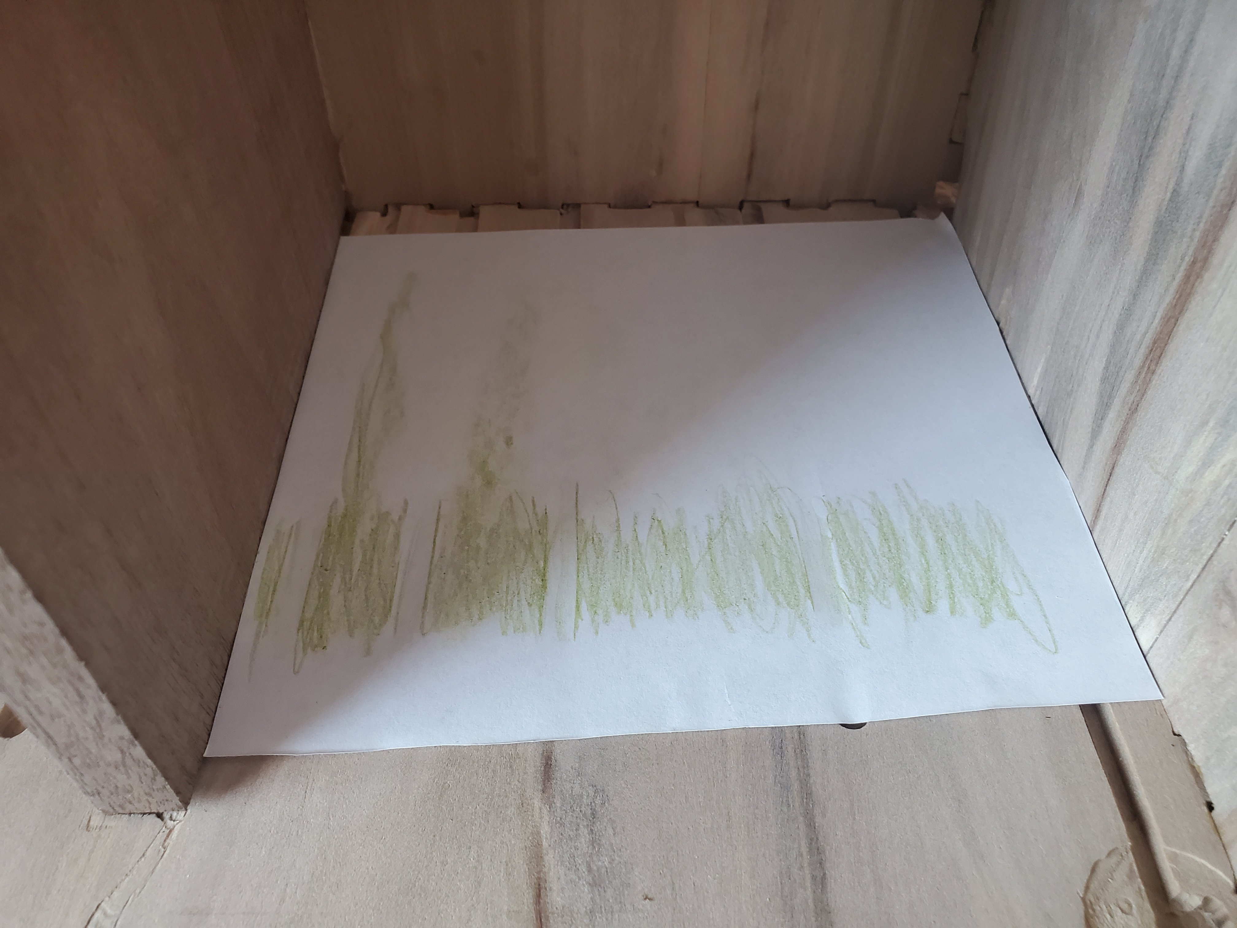
Before I get there, I need to have the internal vertical boards completed.  Transferring the outside slots to the inside slots was something I put off as long as possible because I didn't know how. I had an epiphany one night about how.  I grabbed some paper from the printer, scissors, and a crayon.  I trimmed a piece of paper to fit perfectly in the space that the boards would fit, labelled the paper with where edges were, and then used the crayon to mark the grooves on the paper.


At first, I tried fancy ways of using the paper on the board (cutting out grooves, etc), because the markings on top need to go face down on the other board, or we'd end up with a mirrored board.  I tried folding and cutting the slots with the scissors.


But ultimately, I found it easier to simply fold along the markings, then use a pencil to mark the board, and a straight edge to complete the lines.

The next phase was to drill the panel latching hardware.  Starting with the front panel pins, I needed a vertical (parallel) hole.  Worried about how to do this, I settled on using a square to hold it perpendicular to the drill press table.

While I could install the two internal panels, I thought it would be the perfect time to fill the cracks in the box joints and seal the boxes up.  I dutifully taped everything up, and kept worrying about filling those gaps cut in for the drawer slides.  It took me a night thinking things through before I realized I could lay the box on it's back, open the side seals in order to pour epoxy into those gaps, and let them fill the cracks.  It would allow me to fill up to the back of the boxes and not fill in any of the drawer slide groves.


I needed to take my time on this.  Filling from the sides and letting it nearly set up would allow me to pour another little bit and get things to seal up faster as things cured.  (This was the perfect time to fill the laser-engraving on the front door to match - I did a little mica powder, and a lot of clear, so it could have an interesting effect.)

There was a lot of interrupted epoxy pours. I was using a "deep pour" epoxy made to work with thicker things such as lathe blanks, river tables, and similar things where you need a lot of thickness.  This wasn't because of thickness, but simply because this is both "thin" (e.g. it is very viscous and liquid and can fill cracks easily) as well as long curing.  That alone should allow me to fill all the voids, but it does take a great deal of time to build a suitable base and sealed edges.

Two boxes have have the majority of the voids and cracks filled at this point, so I let them sit for a day or two.  Once I was absolutely sure the epoxy had cured, it was time to sand it back down to flush with the wood surfaces again.

The logos in the front doors came out fantastic, though the silver is a little dark.  I'm not sure what will be needed there.  The gold turned out to be two separate hues of gold - one a little more orange gold (or "antique"), the other being a bright "queens" gold.


There were some areas where I had quite the overfill, because I'd rather make sure we got it everywhere.  I used the tablesaw to trim that off, a grinder to remove large volumes quickly, and then the sander to get it back to where it should be.

The inside was the most painful - I needed a small sander with a corner.  I used a Black and Decker "mouse", and that seemed to let me get into the cracks.  These little sanders come to a point on the tip, allowing you to get into the corners.

Once that was complete, I had to cut 66 small "boards" that were 0.232" thick (to fit into the grooves), 0.263" tall (to protrude as drawer slides), and 6" long (one chest, my "scrap" one, had only 4.875" of space for them, since it was adjusted later because I scrapped a board).  There are three tool chests, each with 11 drawers (that makes 33), and since these require one on each side, 33 gets doubled.  That was fun.  All of those were then glued into place.


Once dried, the inner vertical boards will need to be sanded and have my crooked lines filled with epoxy to match the carcasses, then I can perform the final fitment and glue those in.

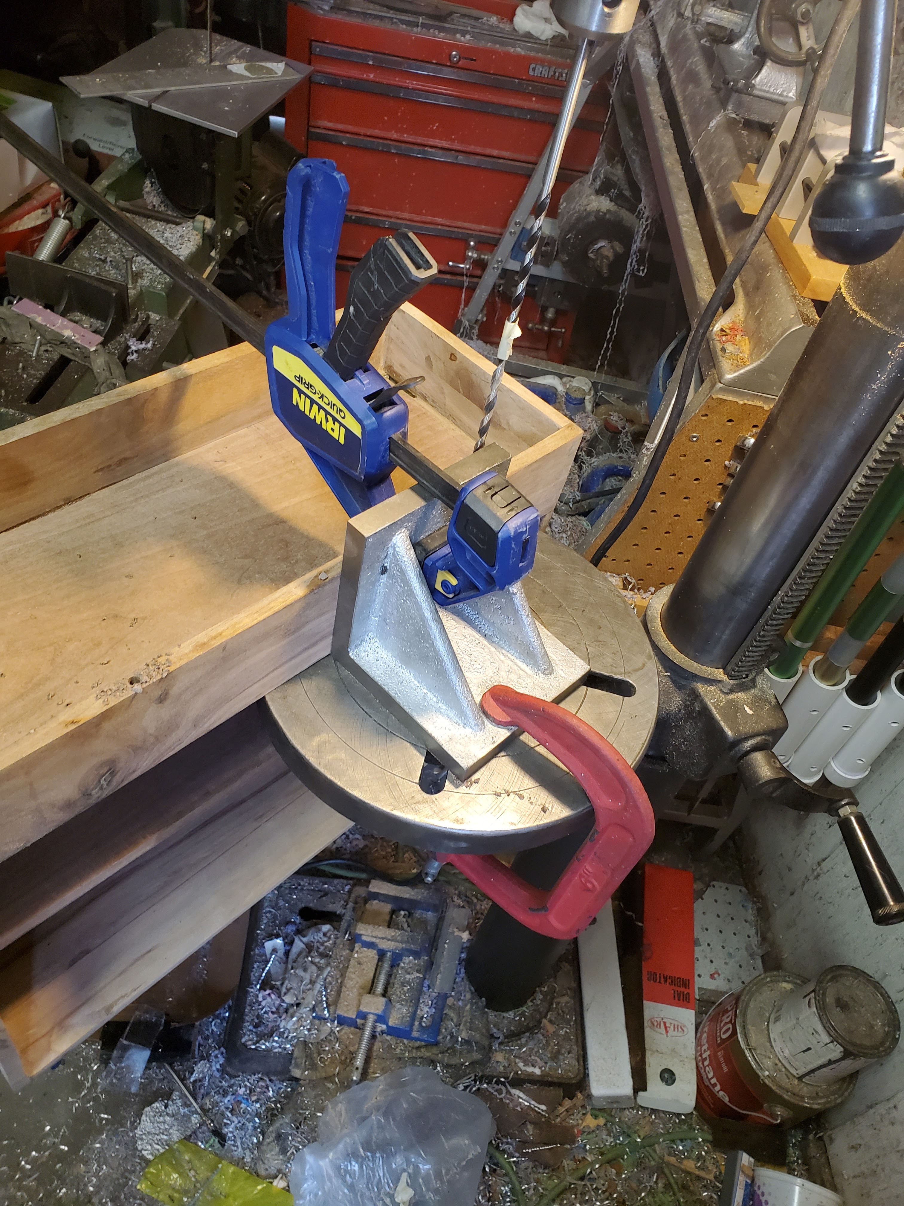
Before I do that, though, I have to drill the holes to house the front panel locking pins.  As I write this, there are a multitude of ways to accomplish a long, parallel hole.  Keep in mind that I didn't think of a better way until I was through two of the three chests, so here we go.

First, I have a drill press table that was trammed in to within 0.002" over 16", so I knew I had accuracy for that one.  I took this to the drill press to bore the face lengthwise the pins.  Here's hoping I'm right and that this works.

This was one operation that took time.  First, if I had any angle instead of parallelism on that front facing bin panel, I'd likely pop out the back.  Second, the drill bit was a longer one (12" long) on a 1/4" bore to fit the springs and pins.  This had to be as perfect as I can, and ended up being the longest set up operation I've ever done.  It took me an hour for each hole (two for each tool chest).  But, I can rest assured that I am as good as I can be.

One additional gotcha was my drill press only has 3" of range, and these panels are anywhere from 3" to 4" (not all tool chests are exactly the same size).  So, I had to drill this in stages.  Painful, really, but I made it.

If you are using the Gerstner pin hardware, the entire bore has to be 1/4" in diameter to house the spring, and the ends are 0.3125" (5/16") for the caps, at least 0.260" deep.  So, drill out with the long 1/4" bit was the first step.

Drilling had to be in stages, of course.

Then, I could finish the drill with a nice, grabby 5/16", 135 degree jobber drill to do a better job of self centering than the brad point bits along that 1/4" bore.  I thought about a drill bit grinder for a 1/4" counter sync, and just decided to wing it.  We'll see in the future if I scrapped all of these in one fell swoop.

After two of the three chests drilled, I was posting over on the machinists forum, and someone pointed out a Craftsman "PortAlign" - an old portable jig used to drill precise holes.  Right there, the lightbulb went off in my head and screamed something about me being an idiot and spending hours on getting things aligned for the drill press, when all I had to do was use a stupid doweling jig!  So, let's do it.


I used a jig that had easily replaceable pins for the hole sizes I needed (1/4" for the through pin bore, and 5/16" for the brass end bushings that keeps the spring and pin in place once installed.  All told, this took me so long in comparison to the drill press method, I was crying (it was 15 minutes for getting the jig set up, drilling the first hole, swapping the bushing, and drilling the second hole to depth, then repeating for the other hole.  A quick flip of the chest to finish the underside 5/16" bore to 0.265" on both of those, and it was done.  15 minutes... is WAY faster than a few hours per each hole working on alignments.

How on earth did I miss that as an option?

The pin drilling is done.  Phew! I had to use the short hand drill for the underside, and as long as I did it okay, I should be good.  Before I can install the inside draw walls, I had to build a new tool.  I went as far as drilling and tapping two ends, 1/4"-28 for a fine thread adjustment (one left-handed thread, the other right) to make a new machinist "jack" that was long enough to make the sides parallel.

I struggled with the right handed thread as the stainless bar became work-hardened in the middle of it.  It still fit what I needed, and I could flip an end around to adjust to a different size.  But it was at this point that I realized that 1/4"-20 (course, not fine) threaded rod and some long nuts would have been sufficient.  So, a quick trip to the big box store (because they had it in stock and I was impatient), and I cut a threaded rod in two pieces and cleaned up the threads on the cut.

With those tools created, I could trim the boards for the inside, and use these crude, long machinist jacks to ensure parallelism of the walls.  First, it was a matter of getting dimensions for the vertical.  This included the entire vertical height, as well as the distance from the bottom (or the top) to the first drawer slide, just so I could make sure they were even.  Making notes :


Then, trim them the last few thousandths of an inch to fit.  Let's glue those in place.


I glued the final strut in place, and let it sit for a day.  The clamps were removed :

I fed them through the router to curve the corners (I should have gotten chrome/nickel corner protectors that were 1/4" radius, but I had mistakenly gotten 1/2" radius).

I did also have to do the final fitment for the front panels, but that went relatively decent.  The process did tell me my table saw sled is 0.8 degrees out of square, so that is an issue for a future fix.  In the mean time, panels have been trimmed.

I spent a few hours sanding to 800-grit (perhaps too fine for lacquer?), and then sprayed the insides of the top bin on both, as well as one side of the front panel.  This was so I could keep it consistent on everything else.  It was three coats on this first phase (30 minutes apart).

 It looks like the gold epoxy actually jumps out once coated.  The darker, "character" walnut seems to pop with the gold.  (Remember, it's not black walnut, this is a combination of sapwood walnut and outer walnut, so it has an extreme grain to it - and it is absolutely gorgeous.)


The silver epoxy, on the other hand, seemed to turn black.


This sat for a weekend, and the following Monday, I shot the final outside coats (three coats at 30 minutes a part).  I let it sit for a day or two, and then I installed the hardware.  This was a make-or-break point - either I was successful up to here, or I could turn this into a junk heap fairly quickly.


Again, the dark and the gold seem to just pop.

This sat for a few days (even though the lacquer was dry in 30 minutes, I just felt like I needed to let it sit a little longer).  Now for the hardware.  First, installing the corner protectors and the hinges.


Next, I needed to get the front panel plungers installed.  These came from Gerstner, since I knew they had a system that worked.  The kit is one half of what you need - e.g. a single plunger, spring, one grommet for the panel, and two brass bushings - I had picked up a few kits when I knew it was for one side only, so two per box.  I glued in the top bushing, let it set up for a few hours, and then glued in the other side.  On one box, I did have to chuck the plunger up into the lathe and trim it down 0.432" because of the size, but they are currently glued up and setting overnight so that I have a solid base to start the latches and handles.


The interesting thing on those plungers is that the lid surface is simply a carpet tack placed in the right spot.  Gerstner did well with what they had - I was thinking I might have to make some brass plates, but finding the tacks in the kits was a good thing.

Next comes the latches and locks.  I debated on installing a key on the brass one.  I'm still undecided, but the latches are all in place.


I must say, these are looking fantastic.  The front panels were simply set in place for the photos.  Before I could call these done, the panels needed to have the hole drilled and the brass grommet installed, as well as the lower hinge hardware for the panel.  I was dreading the panel installation.  It turns out that the installation is documented on youtube by Gerstner.  So, it's off to the drill press to drill the tops, install the hinge plates into the chest, and the hinge pins onto the panels.

First, in go the chest hinge plates so we know how thick to make the panel hinges. Unsurprisingly, it's just appropriately sized tacks that hold it all in place.  Once that is done, install the pins in the bottoms of the front panels that go into those and the panels are the right size (those are drilled out with a #22 drill bit for a tight fit).  I did toss some wood glue in to set up the depth on the pins into the front panel.

The final step is to install the plunger grommets into the top of the panels.  The reason why we do the bottom hinges first is so that we can open the lid, close the panel, and give a slight rap on the pins with a hammer, indenting the top of the front panel with where those go.  Drill them out (I went with an 11/32" diameter brad point bit about 0.040" deep to allow them to be flush with the top, followed by the 7/32" about 0.410" deep).  Then, a little glue to "bed" them into place, pop them in with a light ball peen hammer (the rounded nose allows the grommets to be installed without damaging surrounding finish).

Phew!  It was time for a photo op - these have been a long time coming!


And all three :

Really, this has been a fantastic project.  However, I have learned one thing - if you want a high quality, wooden tool chest, what Gerstner charges for one is well worth it.  The time I have put in (at a standard consultant rate of $70/hour) calculates to about $7,020 (not counting the cost of the hardware or wood, either).  Considering you can get the Gerstner pro-series (the big one) for $2,495 (US), the only thing you get by making your own is being able to say you made it yourself, and Gerstner does sell kits to put together your own that include everything for even less (about $1200 US - I don't know if sanding will be required, or what you'd need to do to complete them).  If you have to go cheap, consider the Harbor Freight "Windsor Designs" chest as it is a fraction of the price.  Sure, it doesn't have the same fine sanding and finish on it, and it's not quite the same size or drawer count, but it will do the job.  In fact, with the push to digital on the Machinery's Handbook, it turns out that Gerstner no longer sells one that can hold a hard copy of the machinist's bible, so the drawer orientation may not even be an issue.

Really, these custom-made chests are keepsakes. They are going to be farmed out to people I know with some specific uses (one was made with more gap between the front panel and the drawers in order to house additional and custom wood panels for what he does, another one is to house some of my fishing tools (rod making, fly tying kinds of things), and the third one is going to someone who has started the dangerous dive into metrology.

Now I have to make 33 customized drawers.  Ugh.