Showing posts with label drill. Show all posts

Saturday, March 1, 2025

Port-A-Lign - Misappropriated For Another Use

I have a need.  There were a number of un-identified reamers that I need to officially know their sizes.  My milling machine doesn't have the reach, and I don't want to chuck up long bars of stock sideways to be drilled.  The best option I came up with was the old Craftsman Port-A-Lign.  It's led to some newer variants, but those were mostly plastic, and I struggled with those thoughts - the Craftsman has the drill chuck centered between the rods, and that makes me think it will be a better option to abuse.

Starting out, I need more length (some of these reamers are much longer than jobber drill bits).  I grabbed the diameter of the rods for this as 0.496" :

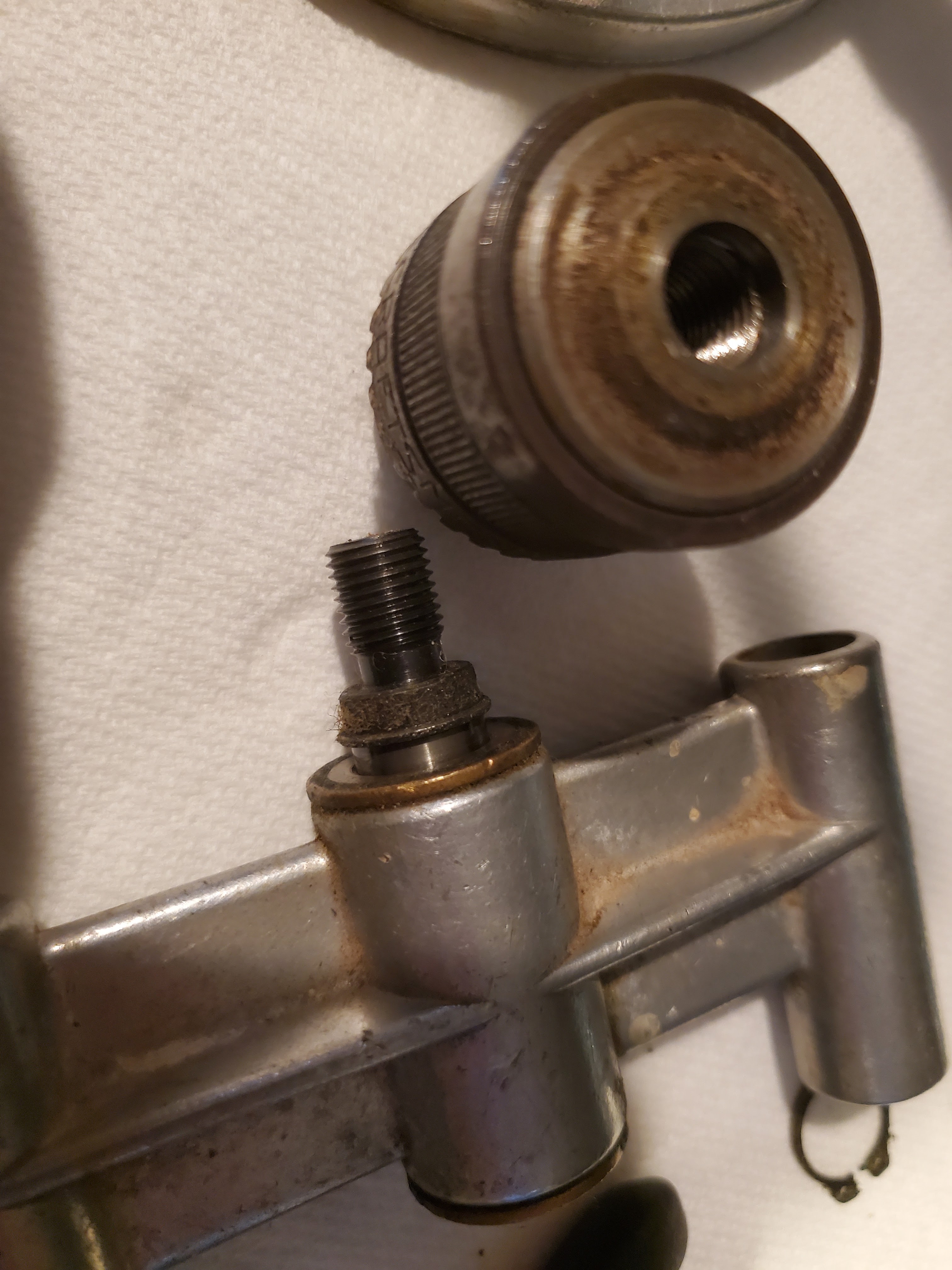
Next up was to identify the spindle that the chuck sits on.  It's a 3/8-24 thread, but I'm missing part, and also the chuck is a 3/8" chuck.  I needed to be able to handle a 3/4" diameter reamer, so a new chuck was in order, and none of those have a 3/8-24" thread mount.  That means I need to make a new spindle, with a JT3 mount on the end for the 3/4" chuck.

I pulled the spindle out.  Two clips hold that spindle in place :


I found a 9mm socket fit perfectly on the end to drive that spindle out.  I got my measurements :

(Not written down is the JT3 taper end, which is 1.2188" long, and the two ends are 0.7461" and 0.8110", or a taper-per-foot of 0.639", and an angle off of center of 1.5251 degrees.)

I chucked the new drill attachment into the lathe (1/2" straight shank, with a JT33 end for a 3/4" drill chuck), and cut a groove down to 0.467" (inside diameter for the new e-clip).  Next the shaft went into the freezer, and the chuck went onto a heater vent to get a good temperature differential for assembly.


So, I have a fully functional Craftsman Port-A-Lign with two interchangeable chucks, the original chuck, and a 3/4" banger for use in first drilling, then reaming a hole.  It's only to test reamer sizes, remember?  Sheesh, my memory has really taken a hit with this chemo thing.


Saturday, March 23, 2024

I Have a Ream

 Everybody knows that drills put holes in things.  Most people assume they are perfect holes - but some people who need accuracy know that is not the case.  So, what kinds of holes, and what to expect?  My brief, inexpertise scale from worst to best :

  • Hand drill - if you need a quick hole and don't care about vertical, size, or anything else, do this.  Even with "drill guide" blocks, you're likely to not get it vertical.  If you are going to thread this hole for a bolt, please avoid this one.  I will throw in cheap drill presses here - though with some work, they can be a little more acceptable toward the next category.
  • Drill press - these are good for getting rid of the above "vertical" orientation issues of a hand drill.  For this category, I'm throwing in drill presses, magnetic drill braces, and I'll even throw in the old Craftsman "Port-Align" attachments to the above hand drills.  They offer better consistency in your vertical alignment.
  • Drill in a lathe - sometimes you can throw the part into a lathe.  These give you MUCH better control over axis alignment, plus the holes become much more - dare I say it - ROUND!  Now, you thought the previous holes were round.  Sure, they were, kind of.  But now we're getting into a much better category and much more accurate concentricity.
  • Boring bars in lathes (or boring heads in mills).  These give you not just a concentric and round hole - these actually let you control the diameters of the said holes.  One drawback of these is the machining marks in the holes, as these are typically single-point-cutter tools that have radii on the cutting end, so while the holes are much more accurate, they still are on the rough side.
  • Reamers.  These are specialty tools designed to give you the best finishes possible, while giving you exactly the dimension you wanted.  The holes are round, concentric and parallel (provided you don't let them wander off course).

Now, I've started thinking through a low-profile, small, milling vise build, and I know I'm going to need better holes than I've done.  So, a "drill" isn't going to cut it, and what I really want are "reamers".  I found a hodgepodge of reamers on eBay that might cover the sizes I need, so I bought it, and classified their sizes (not all are stamped).

So, I measured these, not with actual use, but using some metrology equipment, which means these are likely +/-0.002".  For example, the 0.373 might be a 0.374, and the 0.374 might be a 0.376.  The only way for me to tell is to use each individual reamer, but I'm too tired and fatigued to drill that many holes without good test equipment that I can chuck some of these reamers into without moving drill heads, bases, or anything the like.

For now, suffice to say I have the following sizes in hand :

  • 0.155"
  • 0.183"
  • 0.187"
  • 0.189"
  • 0.218"
  • 0.219"
  • 0.246"
  • 0.280"
  • 0.308" (2x)
  • 0.309" 
  • 0.310"
  • 0.311" (5/16") (2x)
  • 0.354"
  • 0.373"
  • 0.374"
  • 0.382"
  • 0.498"
  • 0.499" (2x)
  • 0.500"
  • 0.515"
  • 0.749"
  • 0.751"
  • Morse Taper #2 (this was a bit of a surprise!)

Next up, trying to feel a bit better.  This could be a longer road to travel before I can get back to projects, but I've gotten this far.  If I can do so, perhaps I can start doing the mill vise.

Saturday, September 9, 2023

Fancy Hex-Shaped Drill Bits

 On one of my projects (the drafting kit), I had a beam compass that I needed to increase the radii on.  I bought a rod to match what it had, and then promptly realized I needed to drill a hex-shaped hole lengthwise.  Nearly any machinist who has been around for a while (I have to say nearly, because it took me a long time to find this out) will be familiar with tools to cut holes in shapes that are not round.  These tools are called "rotary broaches", and they can get pricey (e.g. the bit itself comes in cheaply around $61 from some random supplier found on the ol' Internet).

So, I found a build-it-yourself rotary broach kit and ordered it from Hemingway Kits.  It uses a designation for "FCMS" (or something similar), which is essentially "cold rolled steel".

The tools required for this are a milling machine (the Harbor Freight special will do), and a lathe, along with an M3x0.5 tap.

First is to face, bore and turn the locking lug.  Then thread it (the measured drawings have measurements in metric and imperial, so it was threaded at 52 TPI).

Once done, make the shank.  It is essentially a part made on the lathe, but the mill is used to cut a flat groove 4mm wide for alignment.


Next comes the body - face it, bore it (different sizes to different depths, then turn the outside of it (this is exact).  Once this is done, you will need to cut an internal thread to match your locking lug.

This comes after the lug itself because you want a good, secure fit, and the locking lug can be used to ensure you don't cut threads too deeply on the inside.  In other words, you will fit this to your lug.  Once done, the part is parted (no pun intended) off, and taken to the milling machine where it is set up at a 1-degree angle.  I used a collet block to hold it, so I set a 0.017" lift 1" from one side to give me exactly a 1-degree angle.


Then the back (parted area) is milled flat there, and then a boss is completed flat along that angle to match the groove in the shank.  You have to drill the two holes to bolt the shank and the body together, and then you can tap those holes.  I milled small flats on the sides on opposite ends using the boss as a horizontal index.  Those two flats allowed me to get a solid grip on the body when threading.  Hint - use tapping fluid with an M3 tap.  It makes it much easier.

You might notice the appearance of the aluminum bar with pins and a hole - I quickly realized in a previous step (when fitting the locking lug to the body) that I needed a spanner wrench to match, so I whipped one up.

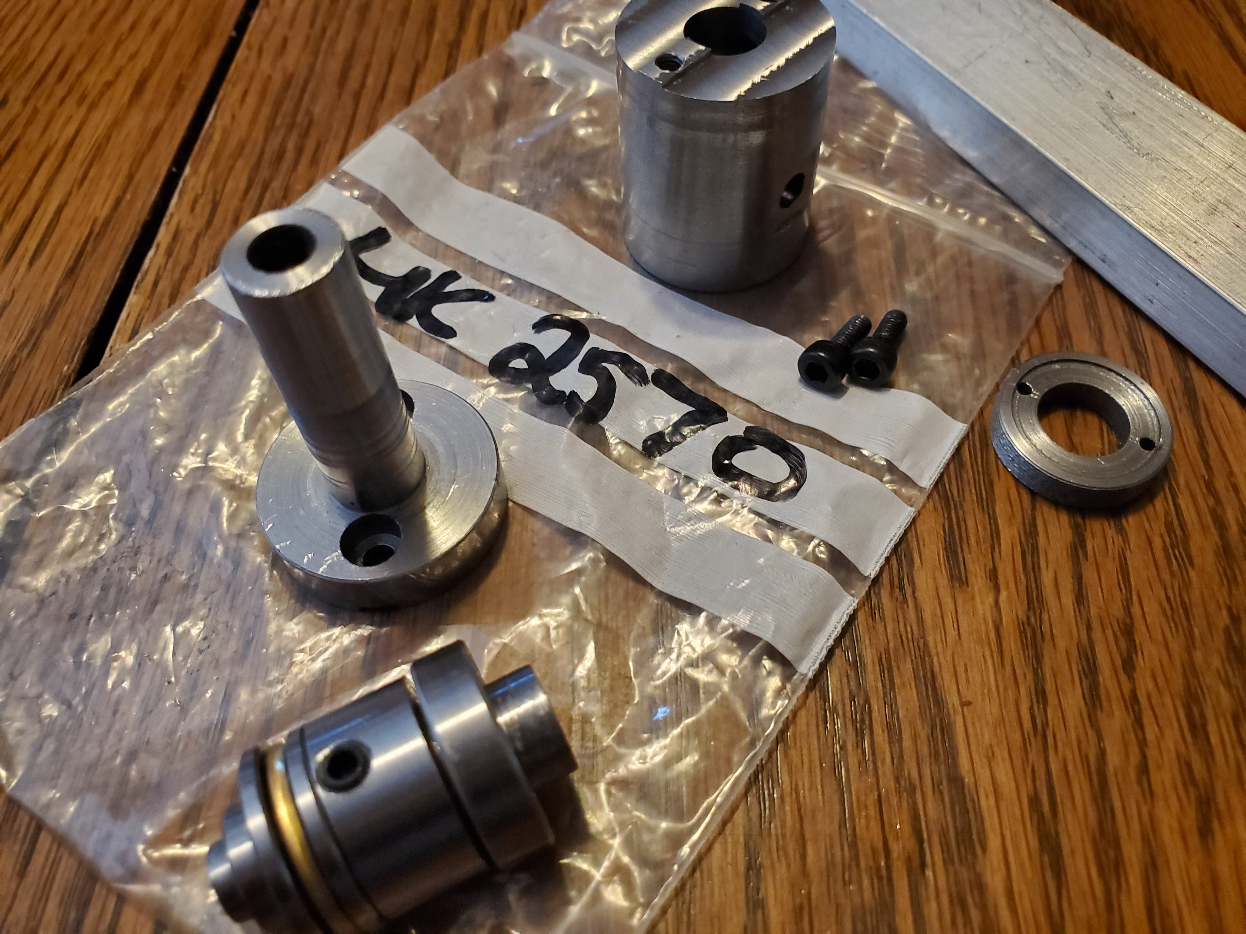
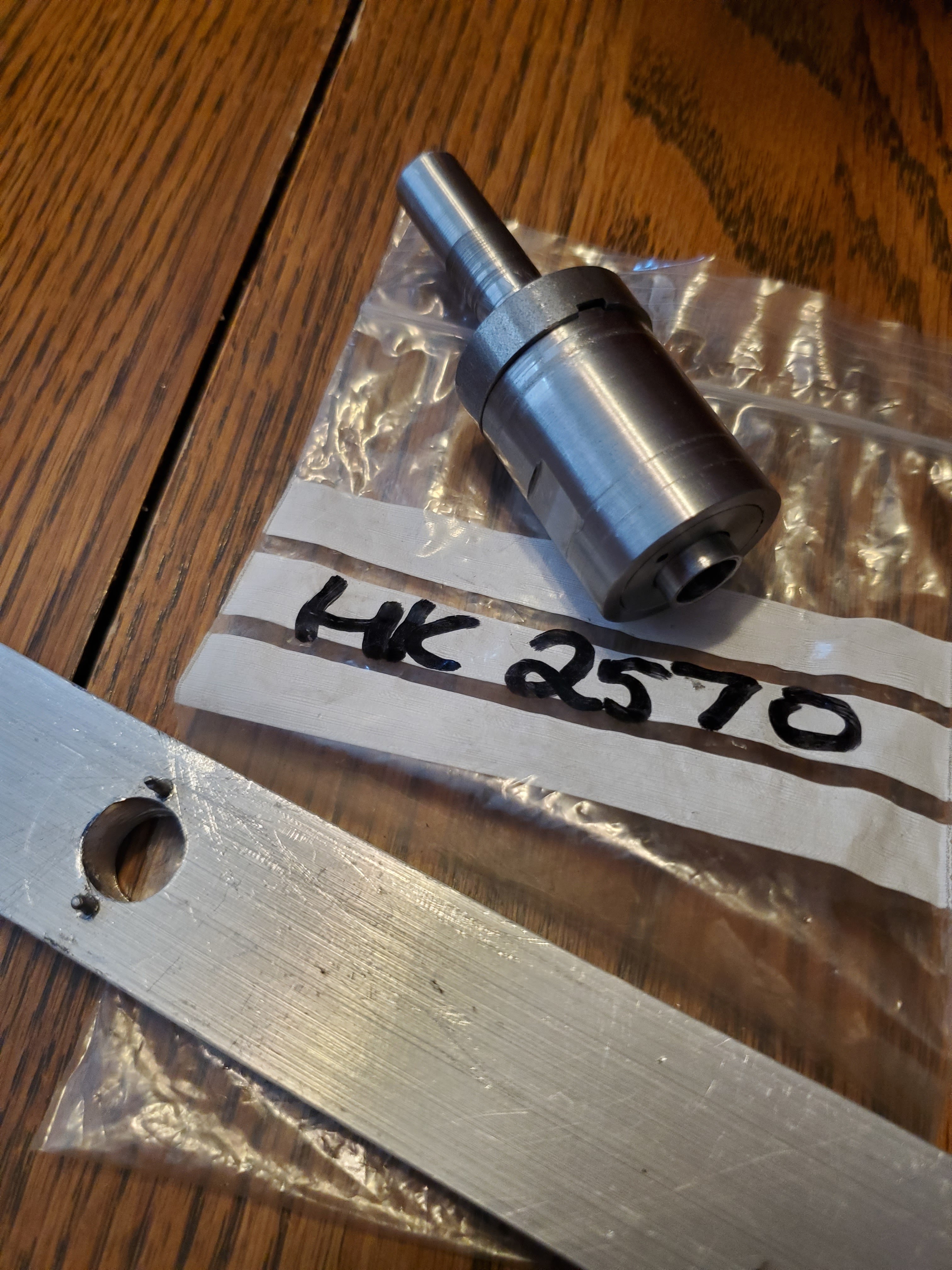
The next part required is the broach's "spindle".  This is the part that actually holds the rotary broach itself.  Following the specs, I slapped it together.  Now, I know I am supposed to wait until I have an actual broach, because angles and math, but I wanted this complete.  Here is the parts, followed by assembly.


After the spindle, I measured, and re-did the math for how long broaches are going to be based on the angles of everything.  After recalculations (and making tools along the way to measure how far I am when I am really close to the lathe spindle), I whipped a broach up.  Quite fun using a hex collet block in the mill at an angle.  It was a bit sketchy - it was a tool makers vise, in a tilting vise.  But, once I got the feel for taking cuts, it went pretty quickly.  This is a 5/32" for what I assume to be a 1/4"-20 drive.

Once shaped, I needed a slight cone.  Most people seem to use a Dremel to grind, but I opted to chuck in a small hollowing wood carbide holder because of it's diameter, and then just used it like a normal tool in the South Bend.

With that, all I need to do is harden the broach and then I can start making car parts again!  I grabbed some brick and a torch, and a jar filled with ice water, and heated it up to red hot (actually, orange hot).  Then just a quick dunk, agitating (shaking it to prevent steam from creating too much of a barrier) it the whole time until it is cool to the touch.


I scraped it against some aluminum, and it definitely scored it.  This thing is, in theory, ready to rumble.  I will to a test cut just to make sure this is going to work before I proceed, but this tool is DONE!

Sunday, October 6, 2013

Steering Column - Coming Together

With some bad engineering drawings, a bad memory, and some skill with Tetris from growing up, I finally figured out how the steering column's Tilt/Telescopic components fit together.  There were a few steps to get me to a point that the Chevrolet manuals talked about :

  1. Find out how the light dimmer switch shaft sets into the housing.
  2. Find out how the turn signal switch connects to the dimmer switch (hint - it uses a plastic carrier that sets into a plastic shell that the tilt/telescopic lever runs through).
  3. Understand how the wiring fits into the wiper/turn signal switch carrier housing (that also houses the ignition lock cylinder)
  4. Locate a suitable pivot pin for the wiper/turn signal switch that connects the switch to the housing.
  5. Put that all together in one fell swoop (you kind of have to do this - without the housing, the parts will fall out, and without the parts in the right place, the housing won't connect.
For the pivot pin, I had lost mine, and found out that no one sells a replacement.  Goofing off, I realized that my Honda Civic (metric) had six bolts for the timing belt cover, and (since I had replaced the engine this year) I had the old bolts laying around.  Those bolts fit into the threads for the housing, and the shoulder on the bolt had a slightly larger diameter (that's a good thing) than what it should be (it wouldn't fit into the switch).  I grabbed my drill, slapped the bolt into the chuck, and grabbed a file.  I basically turned the shoulder without a lathe until it was the right size.

Then I ran out to grab the ratchet to install it..... and found the old pivot bolt still in the socket from nine months ago!  I compared them, and they were almost identical, the original had an extra pivot pin on the end (e.g. two shoulders of different sizes with a threaded section sandwiched in between).  The "replacement" would have still worked, but I opted for the original (anyone wonder why?).

I set about installing everything, and had success in getting those parts completely installed (complete with a new ignition lock cylinder).  Next up, finishing the rest of the assembly, which I can now use the AIM for (the assembly instruction/engineering diagrams at the factory).