Tuesday, May 27, 2025

Folding Desk

There have been a few times where I've had to temporarily set up "shop" (my workstation) in different places around the house.  For example, when we have a visitor and the bedroom immediately next to the workstation is occupied and the time they wake up doesn't match.

These situations have usually had me splitting the expanding table and attaching a dual monitor stand in between the two haves, then pushing back together and setting up in the kitchen.

I have a folding drafting table, and I wanted something similar I could use for a workstation.  I was severely tempted to just purchase a butcher block top along with a folding stand, but if you know me, if I'm going to put one together, I might as well go all the way.  I had some aluminum extrusion laying about for a different project that ended up not being used, so my brain said.... why not?

 I set about designing the desk in my head, and then just threw it together.  Here's what you'll need (with modifications from what I did because you likely will make changes).  Since I was doing this with 2020 series extrusion, my bolts and nuts were all M5.

  • 3 fir boards 2x6 that are 10 feet long
  • Biscuits
  • Wood glue
  • 2x 48" horizontal extrusion rails for the main body (mine were shorter, and you'll see overlap on the folding ends later, which messes with my CDO, er,  OCD)
  • 2x 43" slanted extrusion rail to stabilize the main body (these form the "x" in the main body and stabilize the whole thing - one will need to be cut into two pieces, but do that after the first one is in place)
  • 4x 23.5" horizontal extrusion rails for the folding ends
  • 2x 27" slanted extrusion rails to stabilize the folding ends
  • 6x 26" vertical extrusion rails for the height of the desk
  • 8x 45-degree brackets for the extrusion rail
  • 8x 135-degree brackets for the extrusion rail
  • 16x corner hardware brackets
  • 76 bolts (I had 40 for the piano hinges, so your mileage may vary depending on your hinges)
  • 76 washers
  • 76 extrusion nuts
  • 2x Piano hinges about 20" long
  • 12x extrusion end caps

Tools you'll need :

  • A square
  • Allen keys for the bolts
  • A biscuit cutter
  • A chop saw for the boards
  • A band saw to cut the extrusion to length (and some angled cuts)
  • Panel clamps (I used quick clamps along with off-cut boards to keep flat and Saranwrap to keep those off cuts from sticking to the glued up surface)
  • Sanding pads
  • Planes (optional)

First, cut the extrusion to the lengths you need.

Second, for the slanted pieces, cut the folding ends to 45 degree angles (angles are NOT parallel for these, but opposite of each other).  The main body angles ARE parallel.

Third, start bolting each frame it all (except for the second cross bar in the main body) together.

Once it is all together, you can mark where to cut the second cross bar in the back, cut it, and install that one half.  Then you can line up the other half and mark where that one needs to be cut as well, cut it, and then install it.

With that done, you can then mark where the top bar of the main body connects to the cross bars.  Then, remove the top bar on the main body, and cut those two pieces off, then reinstall the two pieces.  This should keep the whole thing somewhat stable.  That middle section shouldn't be discarded yet - in fact, you will cut a little more off and re-install it about 6" below where it originally was.  This should give you clearance.  (Pictures don't show it offset until you get to the end of this post, and they don't show the second cross bar installed, so be aware).

Fourth, install the hinges (but don't tighten quite yet).  With the folding area in place, open one end perpendicular to the main body and get it square and vertical to the floor.  While in that position, tighten the open ends' hinges to secure it in place.  Repeat for the other folding end.

You should now have a folding rack and desk base.


Yes, notice the folded ends overlapping.  This is because my desk was less than the 48" I've now recommended above.  But it's still "functional".  Anyway, back to the build.

Next, cut the fir 2x6 boards in half.  This should fit the span of the desk.  Line them up in position on the desk surface, and mark and cut for biscuits.

Then, glue it all up and wait.

With the surface glued up, it's time to finish it.  Granted, you don't have to, but you won't be using the desk to write with the way 2x6's have curved corners.  I'd recommend you use the hand planer to get it flat, and then sand and finish.  However, you may want to simply pour epoxy in (sealing the ends, of course) until you build it up far enough to have a flat surface.  My unfinished, but usable workstation :

I used lacquer spray to somewhat seal the bottom (I did not spray the top), and then taped the bottom and edges so I didn't have epoxy run all over.  While there, I also hammered some small gears, screws, etc into the surface.  All of that was filled with a metallic bronze epoxy mixture, then sanded.  I went to 220 grit top, bottom, and edges, then went 800 grit on the top and edges.  Then I lacquered the whole thing (yes, even the bottom again).  Once done, I hit it briefly with 2000 grit sand paper to knock off the little spikes that form (this spray can lacquer isn't the greatest and smoothest finish after spraying).


That gave me a phenomenal surface that won't poke holes in paper, and won't snag on clothes.  It also has a great look to it.  The epoxy will look black or dark unless the light hits it at a specific angle, so everything blends together in a fantastic way. 

I will have to build the nipples for the bottom of the table, the threaded tubes to make it a standing desk, and the fixtures for the top of the stand itself.  I whipped up the specs for machining the 12 remaining parts required (for what I'm doing at least - you COULD adjust with a top hinge and make it only a fully folding sitting desk.  I want the option of standing, so I'm manufacturing a few pieces yet.

I built a fixture plate that bolted to my lathe faceplate (so that I could screw the next part onto it and just make it match), and then did some bandsaw work so I could reduce the amount of turning work I'd have to do, and started cranking through. 


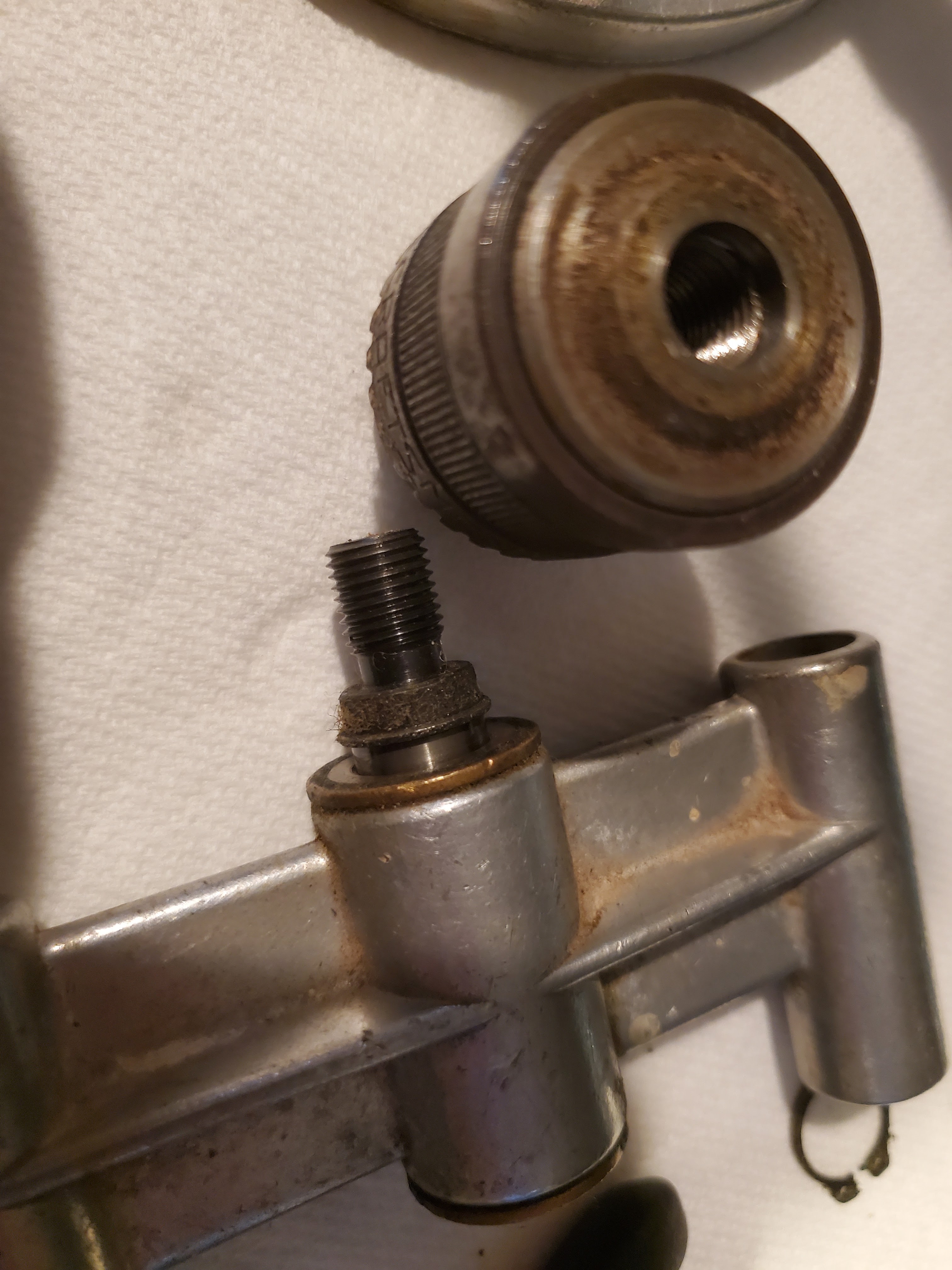
I needed four nipples for the bottom of the desktop, four threaded mounts for the frame, and four pipes with one end threaded to the same thing as the frame mount.  Plus, I had to shorten some M5 screws.

Once these were created, I could install the frame-to-table parts.

Then it to flip the desktop over, line it up, then install the nipples to the bottom.


A final test before I install the standing spacers :

And the final spacers :


I did slap the laptop on it and work in standing position for an afternoon.  This will work well for me when I need to be on the move.


Next, I didn't want to lose the aluminum "standing" rods, so I printed a storage case that simply connects in and locks them when not in use.


Now, I went to use this for a little bit, and there have been some issues.  When it was in "sitting" mode, the height just wasn't quite right.  So, I trimmed off lengths 3" (I already updated the measurements above).  When I tried to use a dual monitor stand that snugs onto the desktop itself, the rear, top bar was in the way.  I added a second cross bar in the main body (pic below), and I cut out the top cross bar and moved that down 6" so I could have clearance for the monitors.  When I threaded the standing-mode bars on, some wouldn't go on all the way.  I ran a threaded die onto them and cleaned up the threads (I had to use an adjustable die so that I could get it perfect, and that meant running it over the threads a few times while adjusting it tighter in between until it fit just right.


I'm loving this thing!  It is now perfectly level, it has excellent stability (though it is a bit heavier), and it all just works as it was designed.

 Now, if I have a mobile Internet connection, we could go just about anywhere and work, and my family can wander off to see sights while I work.  This would be good, as long as the family doesn't get eaten by bears without me.  That would be bad.   Perhaps if I'm eaten by bears along with them, but not without them.

Chess - Ah, Nuts!

A group of chess enthusiasts returned to their hotel room after a tournament, and were still standing in the lobby while bragging about the defeats of their opponents.  After an hour of loud nerds, the manager told them they needed to disperse.

"But, why?"

"Because," he replied, "I can't stand chess nuts boasting in an open foyer."

Perhaps, I had better apologize for the pun. I'm not sorry for it, but I will apologize.

I'm one of "those" kinds of people who loves chess, cars, and I do spend my fair share of time on Pinterest.  I spend little precious time playing video games, and a lot of time just exploring.  And, while in Pinterest, I have seen numerous instances of chess sets made out of fasteners (you know, nuts-and-bolts kinds of things).

Now, a little insight into me in general - I have chess sets.  I have chess sets my dad gave to me when I was 8 or 9 years old.  I have marble chess sets, glass chess sets, wood chess sets (a folding one, and a wall hanging one), and I had a friend make a set for my dad in a machining class out of aluminum (it's anodized blue and clear - it is a beauty).  I'd even made my own by using an existing set and creating molds for the pieces, and casing my own out of green and gold resin (I made a folding chess board back in 8th grade wood shop class - it is definitely rough, but I'm keeping it as is).  I have sets for Lord of the Rings, and I'd like some other resin-cast variations.  Simply put, I LOVE chess sets!

But I do not have my own metal set, and these looked intriguing.  I wanted one.  The materials are not a cheap way to get into the game - trust me, you can find MUCH better options out there (that are even regulation sizes and a bit more portable for things like chess in the park) as cheap as $21.

So, I decided to try my hand at it, just because they look pretty darn cool.  Here's what I ordered :

Repeat the purchase for the other color (I went with black to give it a good contrast - for machining, you basically have brass/gold, black oxide, polished stainless, or just a steel).  I've thrown it all into an amazon list if you are extra lazy.  Just know this is not exactly cheap.

Now, it is time for assembly.

For a pawn, just take 8 of the 20mm bolts, and tighten the acorn nut on as tight as you can by hand.  Maybe a little tighter, but this isn't structural, so you don't need to worry about it being really tight.

For a rook, spin onto the 30mm bolt a regular nut, followed by one of the "castle" nuts (they are officially called "castellated" nuts, and they are used with cotter pins to keep a nut from spinning off of a thread for shafts in things like cars).  Put the peaks upward, and when you have all rooks top nuts in the right position, bring the other nut against it to lock it in place.

For the knights, just thread the lamp rings on.  The improper thread size will lock them in place fairly quickly.

Bishops, treat JUST like the pawns, but with the 40mm bolts.

For the king, just like the rook but with a 40mm bolt.

And for the queen, use a flange nut upside down and a lock nut.


The set doesn't look bad at all in the above photo, (it is incomplete, e.g. the queen is not done).  Additionally, I assembled some black pieces, because contrast between black and gold is just... beautiful.

If you look closely enough, there are still some parts missing (black rooks and king are both missing the "crown", brass queen is missing the flange nut).  Once those arrived, it was relatively easy to complete the set.

Still, I'm debating in my head around making a chess board using gold and black without machining one from stock and going through the black oxide process, etc.  Still working on that thought, but it might ultimately come to that.

Thursday, April 10, 2025

A Dimensional Awakening - An Old 3D Printer (Creality CR-10s)

Since the cancer scare of 2024, a host of old projects are just itching to be scratched [off the list].  One of those projects was my old alarm system needing new hardware around the garage door (the wood it was made out of seems to disintegrate over time).  So, it was time to break out my old Folgertech Prusa i3.

I couldn't get it upgraded to handle ABS, which is where I wanted to go for these parts.  I ran through updates, I adjusted beds, I even bought an enclosure for my Prusa.  ABS was no bueno.

So, I hit the local classifieds and bought an old Creality CR-10 for $75 with hopes of getting it to be my ABS-dedicated machine.  It was extremely dirty, gross, and misaligned.  Plus it was a CR-10s, not a CR-10 (note, not a CR-10 4S - that extra digit and the space make the "s" mean something totally different).  This "s" means it's supposed to be "smart", and has a filament sensor on it which allows it to detect when filament is running out.  There were a few broken parts on it, and a few customizations (e.g. the fan shroud was a dual 5015 fan that was a simple, but really elegant design).

  • First, filament sensor housing had snapped and was loose.  There was a spare piece of filament jammed into it to bypass this, which was okay to get this thing back online.
  • Second, the extruder cooling fan shroud had cracked.  The previous owner had glued it together using superglue glue, but this had failed under temperature.

The housings for both failed parts were after custom, and printed with PLA, which doesn't hold up to heat very well and considering sits around the extruder with high temperatures, is not an ideal material for a fan housing.  But, I think I can deal with a fan that is slightly loose while I use the printer to replace some of it's own parts.

So, I cleaned it up, bought an enclosure, bought a new build surface (the gold PEI plates work best - the black one stuck a little too well and shredded after a few uses because I couldn't get the parts off), and leveled it out.  I started playing with settings and ended up at 255°C on the nozzle and 95°C on the bed. That worked very well for the first few prints (I used real, usable and needed parts as my test prints, such as x-chain links for small parts).

I then backed down to 250°C on the nozzle and 90°C on the bed.  I'm using a brim to keep things as glued to the PEI as possible (again, the gold magnetic PEI build plates seems to be the best as they release when the temperature cools enough, but don't hold onto it like a snake locking jaws in a bite).

I have successful prints.  Now that I know it's ready to repair itself and it functions for what I need, I bought some 6mm extrusion cover in black, and changed this thing to start blacking this thing out.


I have a full x-axis cable support chain ready for a fan shroud housing.  It's time to do the filament detector housing, as well as the fan shroud to connect the x-axis support chain up to.

Bugger.  I can't find the original custom parts online.  I was going to use those because I KNEW they worked.

So, I had to design and build my own.  Out came the calipers, micrometers, and gauge pins to map out and chart the holes.  This was a few weeks of printing and trial and error while I got everything mapped.  First was the filament detector housing. I started with someone elses STL, loaded into FreeCAD, and converted it to a solid to start playing with it.  I angled it up a bit to reduce tension on the filament inside the housing, and ended up with something I liked.

Since I stole someone else's design, I could re-use the same lid/cap they had designed.  I printed it out, and... it warped. Another bugger!  But, it was still usable enough to get that part online.  So, onto the machine it went.  And it was good... for a little bit.  When I started installing the z-chain cable management, not so much.  So, back to the drawing board.  I came up with this thing posted to thingiverse.

Next, I designed the replacement fan shroud.  I used the same tools (FreeCAD, calipers, micrometers, gauge pins) to map out the existing, known-to-have-been-working design, plus I wanted to add the x-axis chain cable support.  I got to where I liked it.

I tried printing the fan shroud, and... it warped so bad it was unusable.  [sigh].

So, I turned off the cooling fans, and reprinted.

There was MUCH less warping (but there was still warping around).  I cleaned it up, and tried to get it installed....


Fantastic!  The third time was the charm!  To finish my x-axis chain, I just need to print the vertical bracket and install it!  This printer is essentially better than when I got it.  The broken parts have been repaired, and additional parts are being completed.  The final fan shroud is available on thingiverse under the name of "Creality CR-10s Dual 5015 Fan with X-Chain Interface" :

https://www.thingiverse.com/thing:7006624

Started working on the cable management (I'm doing all three axis).  One thing I don't like about the x-chain is that if you are using tie-rods to stiffen it up, you DO lost z-axis.  I'll have to address that later.


So, once the cable management was all complete, it is a pretty solid printer.  I really do like this thing.

Now, about that filament sensor.... the next itch that needs scratching is the upcoming "hammo can".  It's an insert for a .50 caliber ammo can that sets up a mobile HAM radio station.  It doesn't fit on this Creality CR-10s with a brim, but the bottom plate is large enough that it shouldn't need one, and without the brim, it just barely fits.  That's going to take 2 weeks to print on this server (and 2.5 roles of 1kg filament), but it's now doable.

Tuesday, April 8, 2025

Pfaff! A New Machine for Me!

305.076.08

I have an amazing aunt (well, my fathers aunt, but I claim her). Every once in a while, she contacts me about a family heirloom.  Well, she knows exactly what I do for kicks and giggles, and when she realized her family had quite a few of these sitting around, she immediately contacted me and asked if I wanted one.

 My first thought was "it's the wrong family", but it didn't take much to twist my arm.  Truthfully, I was twisting my own arm.

I ran and grabbed it.


It is a Pfaff 130.  The machine itself is in surprisingly excellent shape.  It doesn't rotate very well right now completely around, which indicates that something is likely bent inside, or it just needs a good cleaning.  The belt has disintegrated, but other than that, it appears to be well taken care of as there's not a spot of rust on it.  Kudos to that side of the family for taking such good care of their machines.

First things first, I need to try to identify this a little more than just using the model number off the front, because they were made for quite a while.  I found the serial number on the inside, "5 123 825" :


A not-as-easy-as-expected search (took a few manipulations of key words, but that is all), revealed a page out there where Brenda Dean of ISMACS' locale released a basic chart 

https://ismacs.net/pfaff/pfaff_manufacture_dates.html

And that tells me precisely that my new toy was manufactured in 1954.

I went through this thing, and I ordered a belt (some websites linked to this 14-3/4" belt) #305.076.08.  It did NOT fit.  Instead, I opted for a 15-1/2" belt, and with some adjustment, it works beautifully.  The motor and electrical are good to go, and everything has been oiled!

This will let me sew mild leathers for car seats, canvas for carrying cases, etc.  I'm excited for this new toy!

Saturday, March 1, 2025

Port-A-Lign - Misappropriated For Another Use

I have a need.  There were a number of un-identified reamers that I need to officially know their sizes.  My milling machine doesn't have the reach, and I don't want to chuck up long bars of stock sideways to be drilled.  The best option I came up with was the old Craftsman Port-A-Lign.  It's led to some newer variants, but those were mostly plastic, and I struggled with those thoughts - the Craftsman has the drill chuck centered between the rods, and that makes me think it will be a better option to abuse.

Starting out, I need more length (some of these reamers are much longer than jobber drill bits).  I grabbed the diameter of the rods for this as 0.496" :

Next up was to identify the spindle that the chuck sits on.  It's a 3/8-24 thread, but I'm missing part, and also the chuck is a 3/8" chuck.  I needed to be able to handle a 3/4" diameter reamer, so a new chuck was in order, and none of those have a 3/8-24" thread mount.  That means I need to make a new spindle, with a JT3 mount on the end for the 3/4" chuck.

I pulled the spindle out.  Two clips hold that spindle in place :


I found a 9mm socket fit perfectly on the end to drive that spindle out.  I got my measurements :

(Not written down is the JT3 taper end, which is 1.2188" long, and the two ends are 0.7461" and 0.8110", or a taper-per-foot of 0.639", and an angle off of center of 1.5251 degrees.)

I chucked the new drill attachment into the lathe (1/2" straight shank, with a JT33 end for a 3/4" drill chuck), and cut a groove down to 0.467" (inside diameter for the new e-clip).  Next the shaft went into the freezer, and the chuck went onto a heater vent to get a good temperature differential for assembly.


So, I have a fully functional Craftsman Port-A-Lign with two interchangeable chucks, the original chuck, and a 3/4" banger for use in first drilling, then reaming a hole.  It's only to test reamer sizes, remember?  Sheesh, my memory has really taken a hit with this chemo thing.