The table project from over the late-summer/fall/early-winter had a few left-over beams. I decided to try my hand at making a few Gerstner #42 tool chests from some of the boards, in an attempt to flex my woodworking muscles. This is going to be similar to the table top exercise only in a few parts. There are eleven panels for this, and I'd suggest a quarter of an inch bigger in every dimension to ensure that when you are done, you have good sizes that can be trimmed back down :
- Back panel (20" wide x 16" high)
- 2x side panels (16" high x 9.5" deep)
- Top and bottom panels (20" wide x 9.5" deep)
- One front, top panel (20" wide x 5" high) for the top
- One front, movable panel (not glued into the box) (20" wide, 11" high)
- One internal bottom for the bottom inside the lid area (19.5" wide x 9" deep)
- One horizontal, internal drawer separator (19.5" wide x something deep I can't remember)
- Two vertical drawer separators (can't remember any of these dimensions)
The process is :
- Slice the beams into boards (showed how to do that on the table project linked above, and I'm too lazy to show it again)f
- Plane the boards down (just over 1/2" for later sanding to final dimensions) (again, too lazy)
- Rip the boards to length to give clean edges (lazy... sensing a trend here)
- Slice the boards to length for each panel (TL/DR [too long, didn't read])
- Cut dowel or biscuit joints/holes into the boards
- Glue them up
- Apply epoxy resin to fill the nail holes (and other imperfections)
- Trim the boards to both squareness and size
- Cut box joints (a new tool should show up here to cut these)
- Use a router guide (another new tool) to cut the slots for the draw runners)
- Drill holes and cut mortises for panel locks, hinges, handles and actual key-locks
- Test fit everything together
- Final sand all of the panels to prepare for the final glue up
- Glue everything together
- Stain (if that is going to happen)
- Coat with a varnish or other protective layer
- Install the hardware
- Make a lot of drawers
Oh, yeah... I'm making three of them (for a few people). (WHY do I always bite off more than I can chew?)
So, with that let's get moving. I have a feeling (with how long the table top exercise went) that this could be a long project.
I sliced the beams down to length, planed them to thickness, and then ripped them lengthwise to get my basic building blocks.


Next, I sliced them all to length for the panels I needed. Here are two tool boxes organized in "panels" that aren't glued up.

Okay. The next phase was something new. I had a biscuit joiner, but my weird little brain said this was a good chance to try my doweling jig. I took the panels, and I'd drill a hole in the side using the jig to get perpendicular. Then, I'd use the little nub that the jig came with to transfer the drill hole to the next board, and then (using another scrap board in between the hammer and the board I'm marking) I'd give a slight tap to transfer the point to the other board. Then I could use the same jig to drill new holes in the mating board. So, here we go. First, drilling the board :


Then, marking the next board :


At this point, I can glue the panels up. Lots of clamps would have made this MUCH faster, but I could only do one at a time.

I never did the holes in the same places. I had this fear that I'd mix up boards and get grains all wrong, so I intentionally placed the holes at different points along the boards. I put two dowels in the side panels, and three along the lengths of the front, folding panel and the top, bottoms, and the back. That should give some strength instead of a simple butt joint, and make this chest fairly stout and solid. I am doing 1/4" dowels for these, as I'm working in 1/2" wood.
It was at this time I wore my hands out (drilling and transferring holes and drilling the other side for 156 dowel, but who's counting?), and tried biscuit joining them - but that had horrific results. Those panels became the internal panels, because they could be cut a little shorter.
With the panels glued up, and with me organizing as much color grain continuity as I could, I had one tool chest with slightly darker walnut (transition from sap wood to heart wood) and two tool chests with the lighter wood (these are walnut, but not black walnut). With the slightly-darker walnut, I'm opting for brass hardware (which means a gold epoxy), and the other two will be chrome or nickel hardware (which means a silver epoxy). I went with "queens gold metallic mica" by Littarby to be exact, and I went with the brightest silver I could find (just "silver").


The filling process also took as long as the glue up - I didn't have enough work surfaces, and I could only do one surface of each panel at a time (there are 6 for each panel - both faces and four edges - but I always left one edge along the grain exposed for a base surface to use when trimming to size later).


This, alone, was about a month in labor, continually mixing up epoxy, vacuuming the bubbles out, and pouring it over every single void (or crack where the edge wasn't lined up perfectly when ripping to length), and repeating for the same surface until the cracks and voids were full. I'm not using a fast cure on epoxy, primarily because I want to give it time to slowly get into the cracks - essentially, I want every void in these boards filled with epoxy.
On edges where a crack transitioned to, those also mandated a surface for pouring (and there were a few). All cracks on the edges were filled, and most of the end-grain was also filled as much as I could get. I did this by taping the ends, standing the boards up, and pouring into the tape "moulds".
Once the epoxies had cured, I could finally get to the sanding. This was a bit annoying - because I already sanded previously (after gluing) so that I could find the voids. But, I have to do it again. I'll do the finish sanding after the routing for the drawer guides/runners.

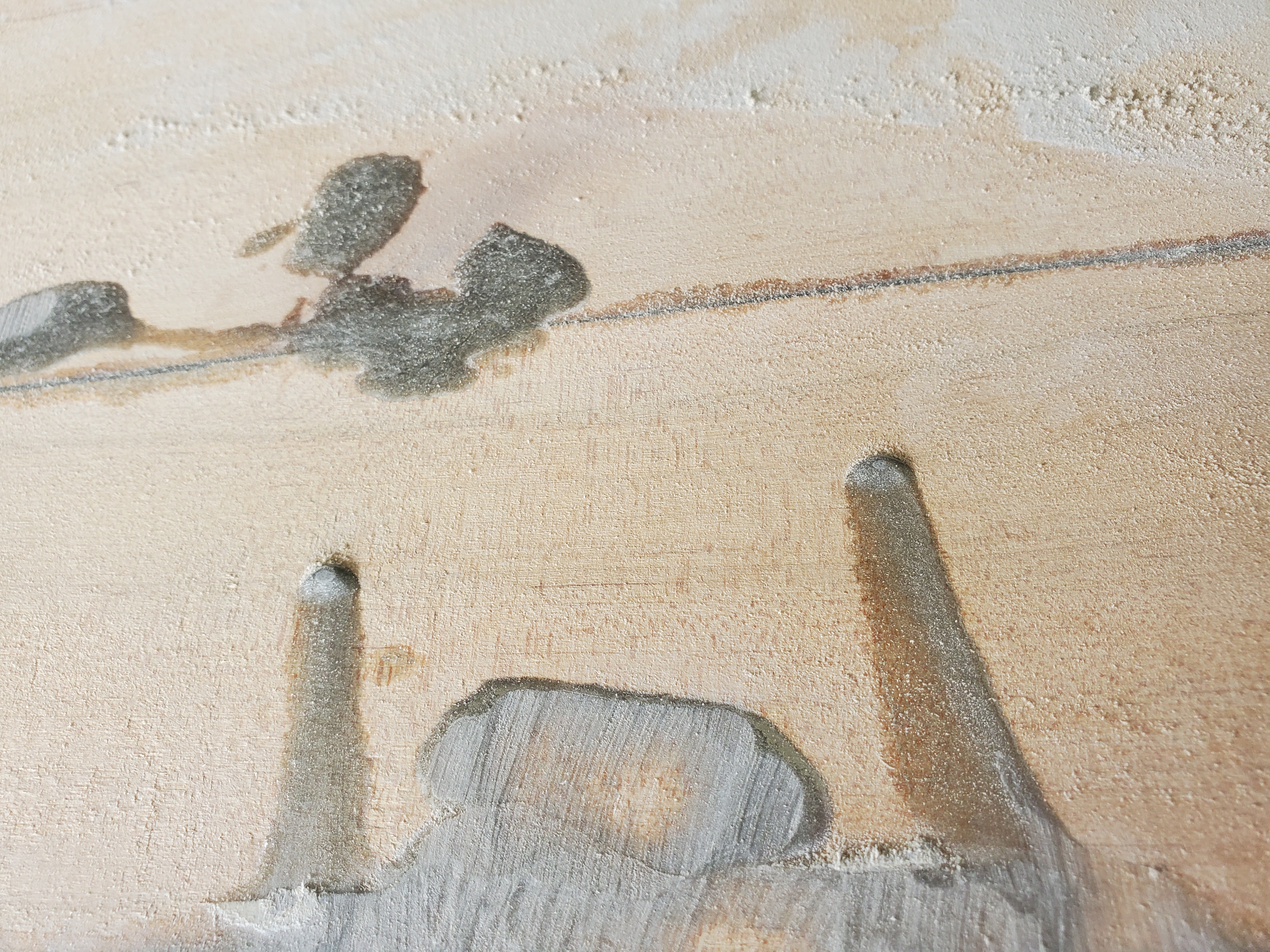
Unfortunately, there was a snafu in which one of the boards was epoxied to the clamping boards, and releasing it snapped and cracked one of the side panels (not along the glue line, either - that joint seems to be holding well enough). You can see the crack in the above photo. This was epoxied together to get a good fix. At one point, I also broke one of the sides - this was glued together (with a biscuit to give the joint as much strength as I could).
There was so much sanding to be done that I ultimately used a grinder to knock large swaths of epoxy down to "close enough" before engaging the sander.

You can see in the pictures above that I have three piles of boards on my workbench. Each pile is a matched set of panels.
It was a lot of sanding the epoxy used to fill cracks down, but the day that happened was a BIG day!
Once the sides were sanded, the boards could be cut to final dimensions on the table saw. Each board had a single, good edge at this point. I'd first cut the parallel lengths for each board with that length, then I would move on to another dimension and cut all boards for that one (on all panels). As each cut was made, a mark was put on it to know which ones were done. The marks were in pencil so that they could be sanded off once the box was glued together.

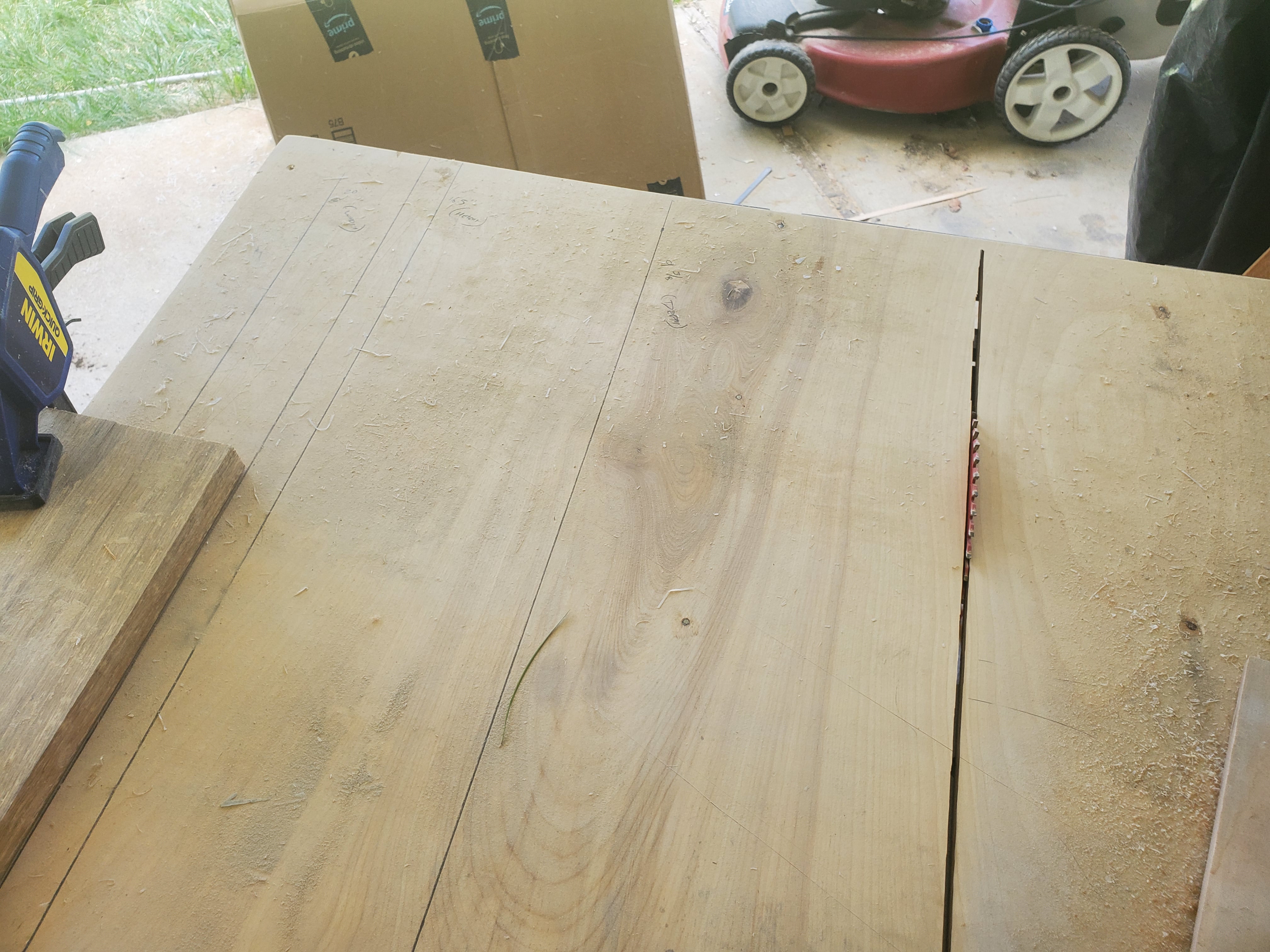
If you look closely at the last picture above, you can see I put marks for widths of each panel on my panel sled. It's a technique called "story boarding" - you write down exactly what will happen, and then you make it happen. I would set one width, mark it, put the stop block clamped down, and then make ALL of the cuts that were the same dimension. In other words, every single width was cut. Then every single depth was cut. Then every single height was cut.
The result was a set of panels that were perfect in every way except for... the depth.
[sigh.]
The depth, because of the narrowness of the dimension (supposed to be 9.375" or 9 3/8"), I chose to use the fence instead of my marked story board sled. Unfortunately, I measured to the same side of the 9" mark, which actually turned out to be 8 3/8". That meant each of these boxes is going to end up 1" shallower than what they were patterned after. Oh, well.
With the panels all cut to size and prepped, I could then cut the box joints. I had picked up a Rockler jig for cutting box joints on a router table, and before fully engaging, I had to finish the jig. It requires one pass with the cutter you want.


At this point, I needed to do some careful planning. I didn't want to mess these up. So, I had to use some left-over MDF (it was 1/4" thick, but I'm testing for 1/2" thick - gonna have to glue some boards up) to cut some test cases just to see. I have a couple of oiler cans that I've been collecting, so I decided to use this MDF as a shelf when done. I've intentionally cut the depth a little too deep, so that I have a slight forked lip all the way around the shelf to keep the oil cans on the shelf when we have another earthquake roll through.
The part that I was most worried about was the corners where three panels met together - and this little test candidate was perfect for the test. First, glue two "boards" together to get the 1/4" to 1/2" thick (matching the tool box panels).

Each of those boards were fed through the table saw to get them square and to size. I had three boards the exact same dimensions. One would become the "back" (toward the bottom, used to attach the shelf) for attachment to the french cleat, one would be split into sides, and the last would be the actual shelf.
It's time to cut the box joints. It took a while to get the jig set up, because it kept changing on me, and wouldn't line up. (Widths kept growing.) It resulted in a lot of scrap tests completely failing.


So, I punted. I found the device kept sliding, and the dimensions would change with each cut, too. I grabbed some brass shim stock, and slapped it into the grooves that the jig attached to.

The shims allowed the jig to stay in place long enough to cut a longer edge on both sides. It was still tight, but it worked.


Next up, I have to get back to my test case - the oiler shelf out of MDF. I ran 4 edges of 24" long edges through the jig. I also grabbed the side edges (both sides), and then glued it together.
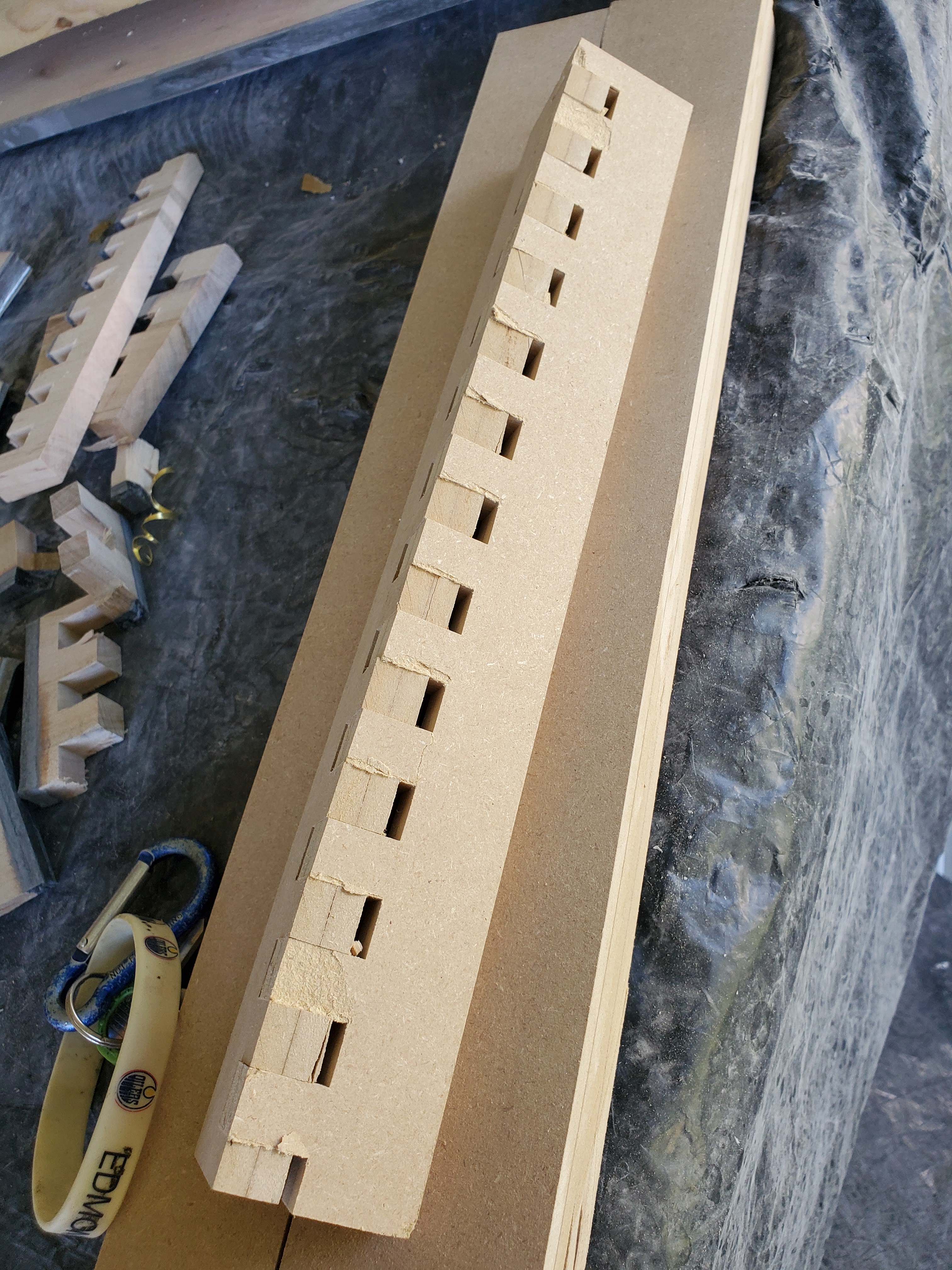


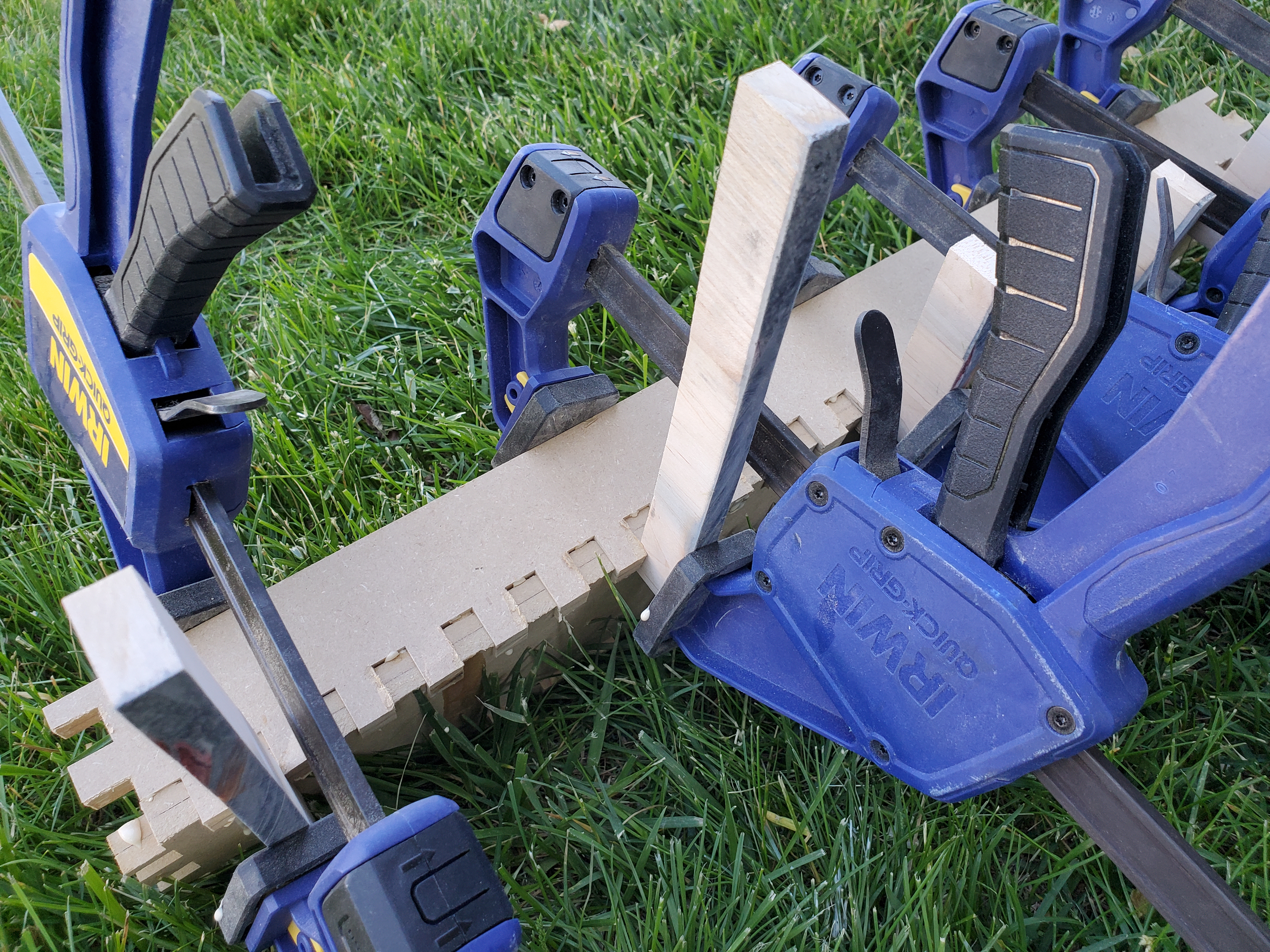


If you look closely, you'll see a gap on one end. I completely put one single board in the wrong way. [sigh]. Assembly will be critical.
The other thing that I learned (which is why I did the test) is that, on a box-cut corner where three sides come to a point, the actual corner is not complete - there is a small chunk of wood that is not in place. It's a side effect of box cutting, really, if you think about it - three sides, binary on/off. Anyway, I can fill the corners with epoxy before rounding everything off, so I think I'm going to be fine.
Now I can engage the REAL box cuts, knowing that I have to reset the jig after every long edge. Lots of box joint cutting, each mating surface at it's own time (e.g. cut one edge of a board, then cut the same edge on the adjoining board). In this way, the joints should be going to be perfectly aligned. I went through each set of boards and marked every single edge.


I now have three piles of boards, one for each chest. Now, on to the inner routing that needs to happen. I have to cut grooves for two horizontal (bottom of the lid, and the separator for the drawers). This will need to be the thickness of the boards. Before I could do anything, I ran a test. I anchored the aluminum angle that I'd be using as a guide, and ran the router. I could measure the distance from the angle to determine how far I needed to get the cut where it should go. I needed 2 3/32" with a 1/2" router bit.

Okay, now I can cut the shelf support grooves.


I only hosed up one tool box and got a groove on the other side. Yay! I'll just fill that apprentice mark with some epoxy, and everyone that sees it will be completely the wiser (too easy to know what happened - it's on the outside).
The next groove I needed to cut was the bottom one for the front panel to slide in. This was a bit difficult as it was 0.397" from the bottom board, and 0.197" in diameter. I don't have anything in that diameter - even a 3/16" router bit comes in at 0.1875". I settled for the 3/32" router bit I picked up explicitly for the drawer runner slots (more on that later), and then did a lot of math until I had the right numbers. Then I could set up a piece of angle and cut the path. It would require three passes with the 3/32" bit (3/32" is slightly less than half of the 0.197").


While there, I routed out the metal frame so I could inset that. Gerstner sells the little front panel pivot point that keeps the wood from splitting out when people abuse it. I'll need to order two more of those (for the other two chests).
Unfortunately, the box joints didn't quite line up perfectly. I had to manually fit each joint by hand using a rasp, a Japanese pull saw, and sandpaper glued to a 1/8" metal bar that fit between the pins. I gotta tell you, for joinery, those pull saws are amazing. I'd set the edges together that were to be joined, and transfer lines from one to the other board just using a pencil on the edge. The pull saws could make some very thin slices, and things just came together quickly.
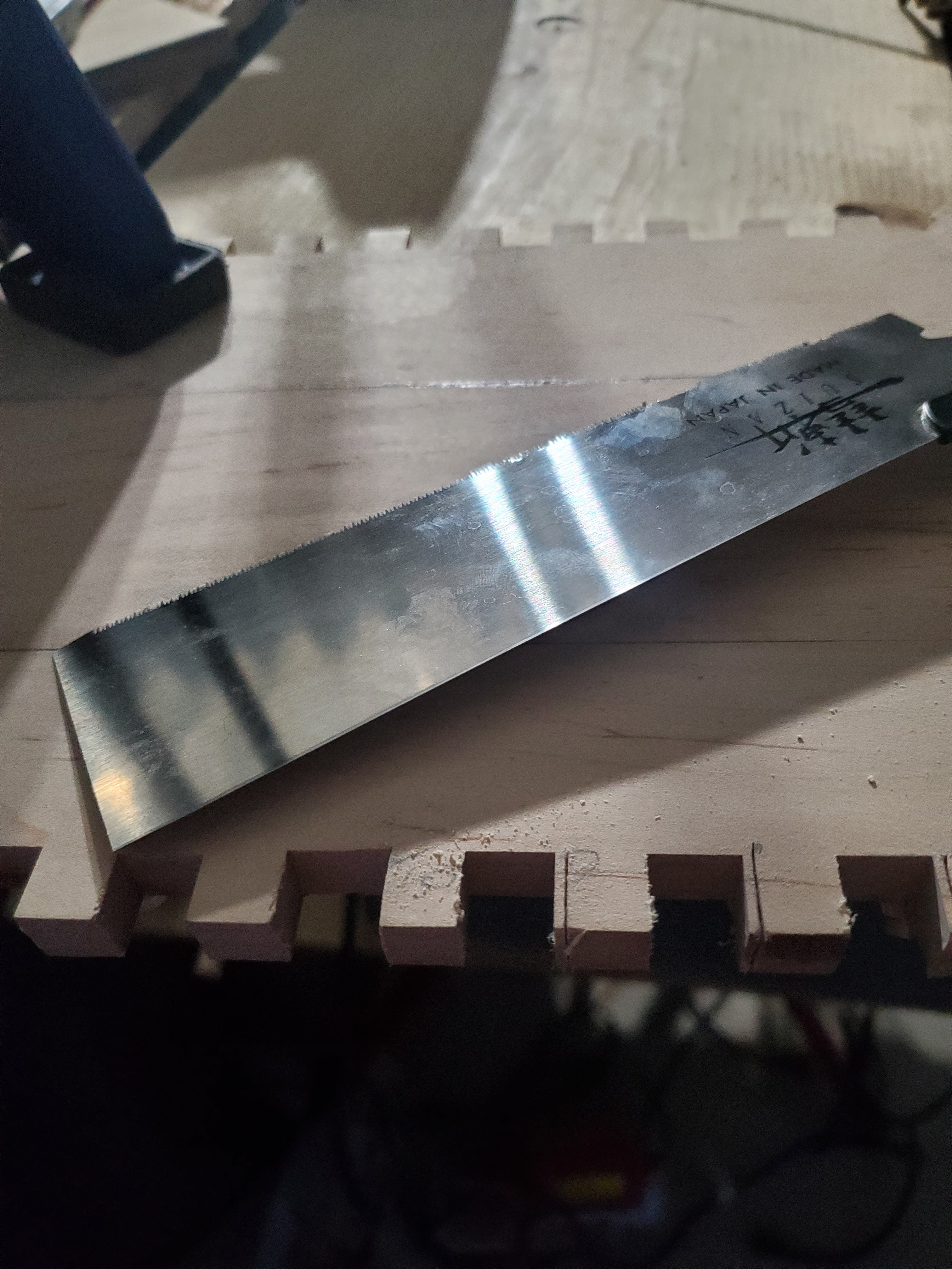


Three boxes' worth of hand sawing various tenons for these box joints was excruciatingly time consuming. The rasp, hand sand bar that fit in between the tenons, and the pull saw/coping saw combination did the job, but it takes a while to line everything up. When the day came that these were done, I was ecstatic. I still wasn't remotely complete.
My next task could only be done assembled without being glued. I needed the actual inside dimensions of those grooves I'd cut. Sure, I can measure where things go, but with the difficulty of things potentially not lining up, I am going to make absolutely sure. So, I put the boxes together and slapped some measuring "bars" in place.


Granted, because I don't trust the tape measure on the inside of a tool box where I need to measure the groove, so I used a 1/4" piece of MDF. Then I could measure the gap using the telescoping snap gauges (yes, a machinists' tool rears it's ugly head). Each box has to be assembled and checked for this dimension so I can cut the drawer supports.

With these measurements, I could now cut the bottom board for the top area, as well as the drawer supports. First was the top, because it is very simple. It's just a rectangular board. The horizontal drawer frame was easy to, but it needed a rabbet. And, once the rabbet was cut, I could then cut the two vertical drawer supports to match. But, alas! There not enough wood here to finish the supports for the drawers!


The next task was routing the grooves for the drawer runners. This task turned out to be a lot of math. First, I had to determine the distance from the router flat surface to where the router bit actually cut. Then, I had to calculate for each box where to set up the jig (e.g. distance from the top or bottom), and then route each one. I had to use my wood working machinist square because it had 16" of room for me to play with.


With them routed, I have three piles of chest carcass.

The next step was to sand all the inside surfaces (because I wasn't going to be able to sand them once glued up). I went to 320 grit, using the old carpenters trick of using a pencil on the surface of each run and sanding until the pencil marks are gone. Once that was sanded, it was time to glue things together.


I messed up on one side, and had to use one of those fancy orbital saw thingies. With a 3/8" blade, it cut a 1/2" slot, which matched up perfectly to the 1/2" box joints. Unfortunately, after that, I was using a chisel, and (while intentionally trying to keep my wrist out of the way), slipped. An involuntary reaction jerked my wrist right into the path of a sharp chisel.

The doctor was kind enough to tell me how to remove the stitches on my own (which I did - I didn't want to see anyone). So, on to finishing the glue ups of the tool boxes.


The next step was to cut the tops off.
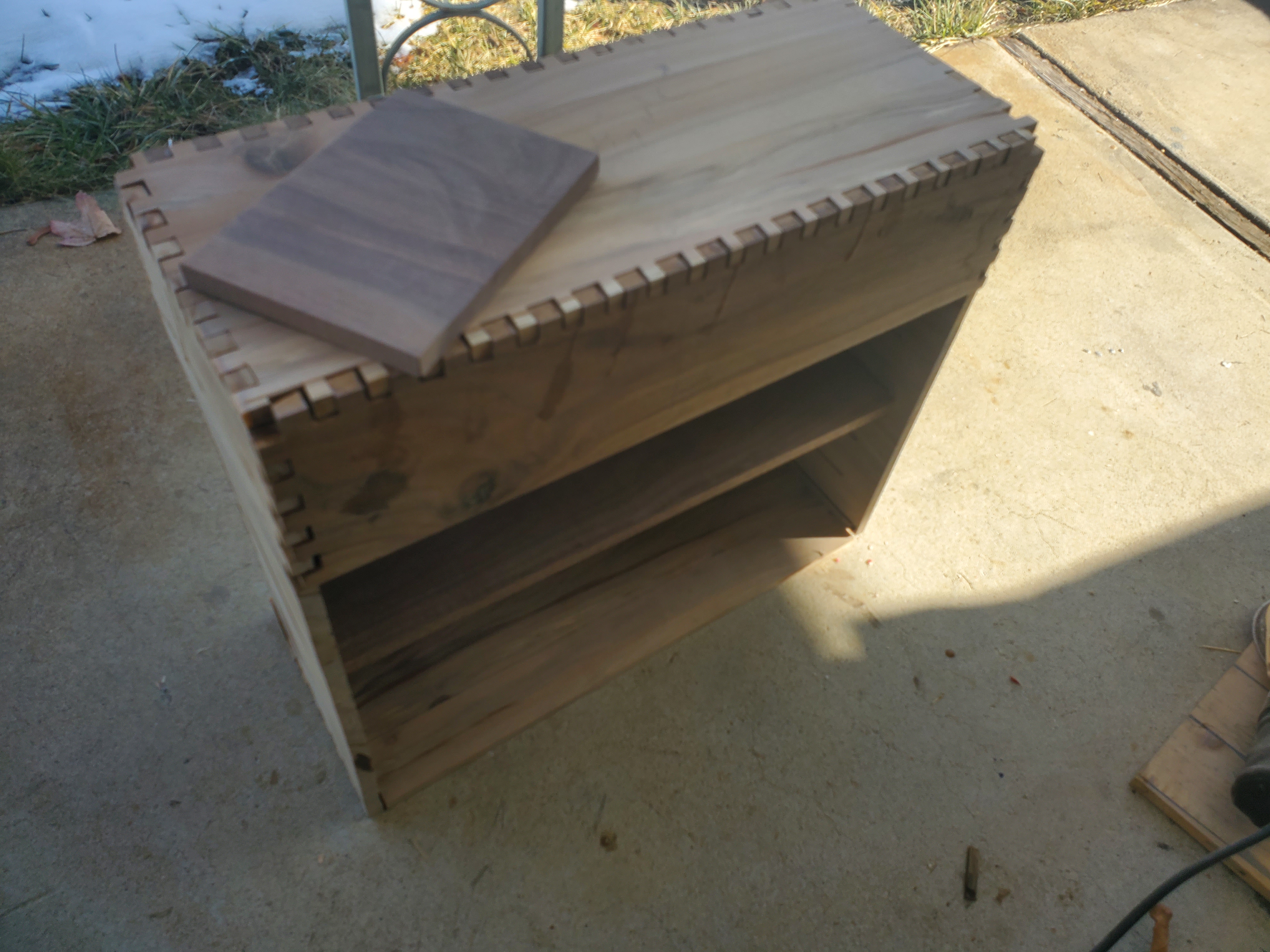


Now, I should be able to fill the box joint imperfections with epoxy to match (one box in gold, two of them in silver). I also used a laser engraver to throw my makers' mark on the front panel (inside) on each one. You can see it in one of the photos above. I'll use a wire brush to clear out charcoal, and then fill it with epoxy resin to match the rest of it. Then I can do the final sanding and the hardware installations. (I did mark the plunger dimensions on each one.)
However, this post is getting very long, so I think I'm going to split this into two posts. See ya on the next post!